XBee® Wi-Fi RF Modules
© 2013 Digi International, Inc. 27
Serial communications depend on the two UARTs (the microcontroller's and the RF
module's) to be configured with compatible settings (baud rate, parity, start bits, stop
bits, data bits).
The UART baud rate, parity, and stop bits settings on the XBee module can be
configured with the BD, NB, and SB commands respectively. See the command table in
chapter 10 for details.
In the rare case that a radio has been configured with the UART disabled, the module
may be recovered to the UART operation by holding DIN low at reset time. As always,
DIN forces a default configuration on the UART at 9600 baud and it will bring up the
module in command mode on the UART port. Appropriate commands can then be sent
to the module to configure it for UART operation. If those parameters are written, then
the module will come up with the UART enabled, as desired on the next reset.
SPI Communications
The XBee Wi-Fi module supports SPI communications in the slave mode. Slave mode
receives the clock signal and data from the master and returns data to the master. The
SPI port uses the following signals on the XBee:
• SPI_MOSI (Master Out, Slave In) – inputs serial data from the master
• SPI_MISO (Master In, Slave Out) – outputs serial data to the master
• SPI_SCLK (Serial Clock) – clocks data transfers on MOSI and MISO
• SPI_nSSEL (Slave Select) – enables serial communication with the slave
• SPI_nATTN(Attention) – alerts the master that slave has data queued to send.
The XBee module will assert this pin as soon as data is available to send to the
SPI master and it will remain asserted until the SPI master has clocked out all
available data.
In this mode the following apply:
• SPI Clock rates up to 6 MHz are possible.
• Data is MSB first
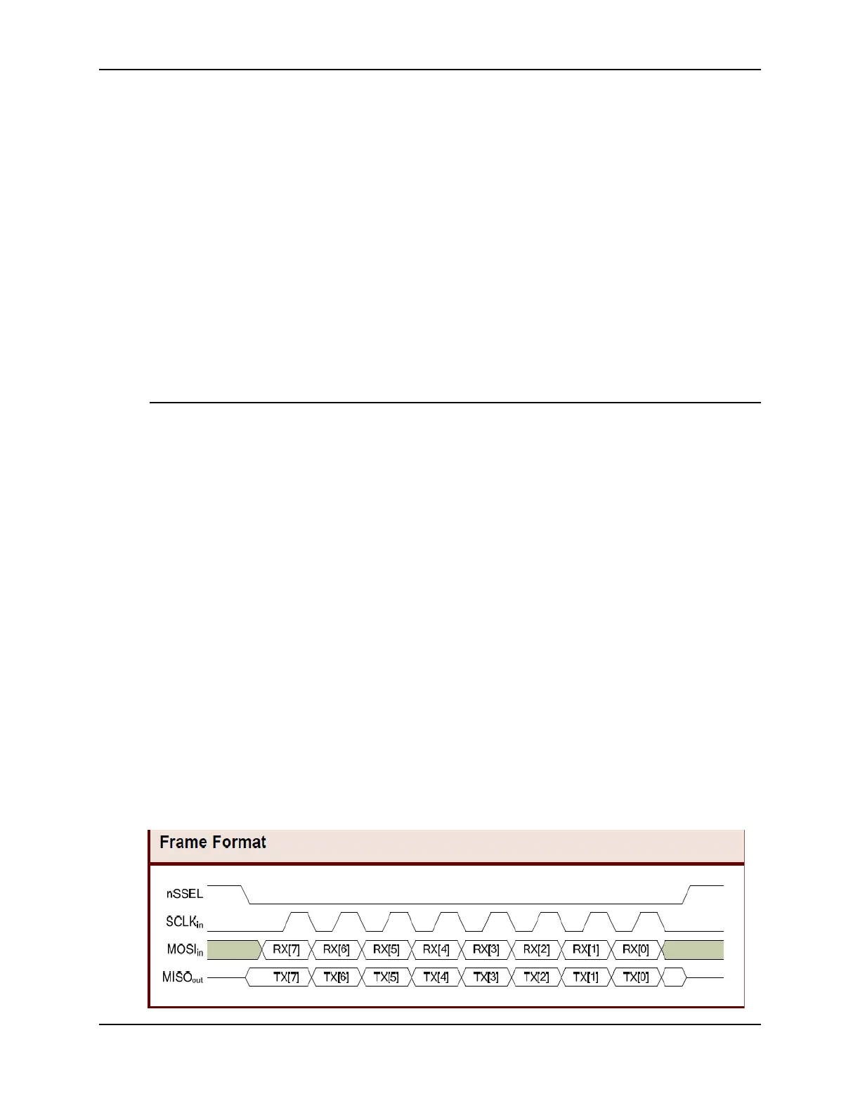
• Frame Format mode 0 is used. This means CPOL=0 (idle clock is low) and
CPHA=0 (data is sampled on the clock’s leading edge). Mode 0 is diagramed
below.
• SPI port is setup for API mode and is equivalent to AP=1.
Frame Format for SPI communications

 Loading...


