- 52 -
LP Engine G430(3.0L) Igntion System
Module
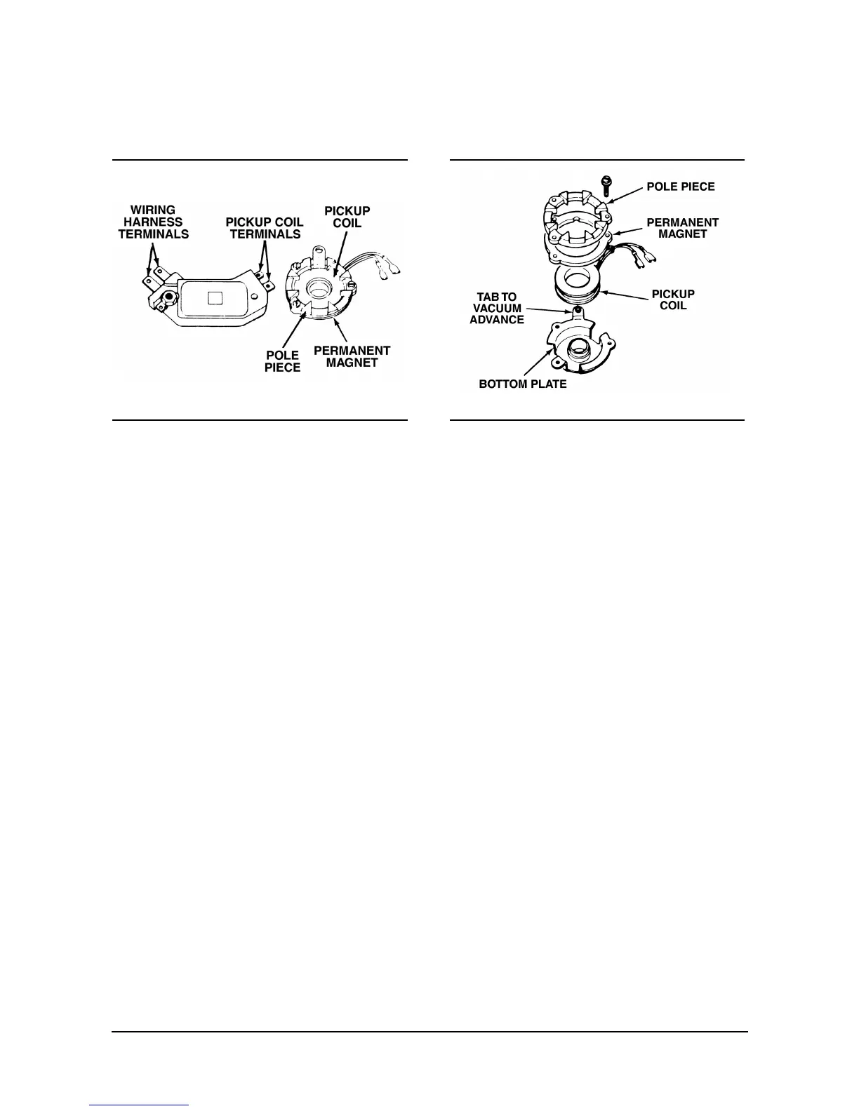
Figure 6-2 Module and Pulse Generator
The system uses an electronic module and a magnetic
pulse generator to control primary circuit current
(figure 6-2). The electronic module has several
integrated circuits that contain resistors,transistors,
diodes and capacitors. These circuits and components
are small enough to allow the module to be mounted
inside the distributor. The ability of the module to turn
the primary current on and off is due to the transistor.
A transistor is an electrical device that is used to
control current flow like a mechanical switch except
that it is turned on and off by electrical current and has
no moving parts.
Pulse Generator
Figure 6-3 Pulse Generator Construction
Since a transistor is turned on and off by electrical
current, a properly timed electrical pulse will control
the primary current in the ignition system. The
magnetic pulse generator, or magnetic pickup
assembly, consists of a permanent magnet and a
pickup coil. Both are sandwiched between a pole
piece with internal teeth and a bottom plate and held
together by three screws (figure 6-3). The bottom plate
then fits over a bushing which is installed in the
distributor housing.
131-059131-058
 Loading...