- 71 -
LP Engine G430(3.0L) LP Fuel System
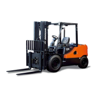
The converter is a combination regulator and
vaporizer. It receives liquid fuel through opening (1) at
tank pressure from the fuelock. The fuel is available
inside converter vaporizing chamber (9) when
carburetor vacuum is felt in converter opening (8).
When vacuum is not available at the fuelock or
opening (8), primary valve pin (3) puts force on
primary regulator valve (2) that makes a seat against
an inner passage for the fuel inlet. The pin action is
controlled by primary diaphragm with lever (5) and
cover (6). Primary spring (13) is in compression when
vacuum is not available.
Converter Secondary Components
(1) LP fuel inlet opening. (15) Secondary lever assembly.
(16) Secondary regulator seat.
When the engine is running, the solenoid on the
fuelock allows fuel to flow from the fuelock to
converter opening (1). Vacuum is felt through
converter opening (8) from the carburetor. This vacuum
pulls in secondary diaphragm (7) with the diaphragm
link, which moves secondary lever assembly (15). The
secondary lever assembly moves secondary regulator
seat (16) that opens fuel flow passage in chamber (9).
At the same time, the vacuum flows through sensing
opening (14) that causes primary diaphragm with lever
(5) to pull in. This causes the diaphragm lever to make
a pivot on cover (6) fulcrum (pivot point) (4). Primary
valve pin (3) moves away from primary regulator valve
(2) with the assistance of primary regulator spring
(13).
When primary regulator valve (2) is off its seat, fuel is
permitted to flow into vaporizing chambers (9). The
fuel flows around and through the passages of the
vaporizing chambers while the heat through the
converter body is being taken in by the fuel which
causes fuel to vaporize. The heat is a product of the
engine coolant that goes in opening (12) and out
opening (11). The flow of vapor fuel goes out
opening (10) in the converter body, activated by open
secondary regulator seat (16) to fuel outlet opening
(8), through the fuel line to the carburetor.
The vaporizing chamber decreases LP fuel pressure
from the tank to less than atmospheric pressure.
This expansion of the pressurized liquid fuel into
vapor, can result in freezing. The heat from the engine
coolant increases the temperature of the fuel in
vaporizing chamber (9) from approximately -42°C (-44
°F) to +2 °C (+40 °F)
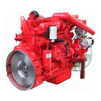
Fuel Tank
LP Fuel Tank
The fuel tank is made of heavy steel. The specific size
of the tank is measured by the design of the lift truck,
desired period of time the lift truck is to be operated
before the tank has to be filled and how near an
available supply of fuel is.
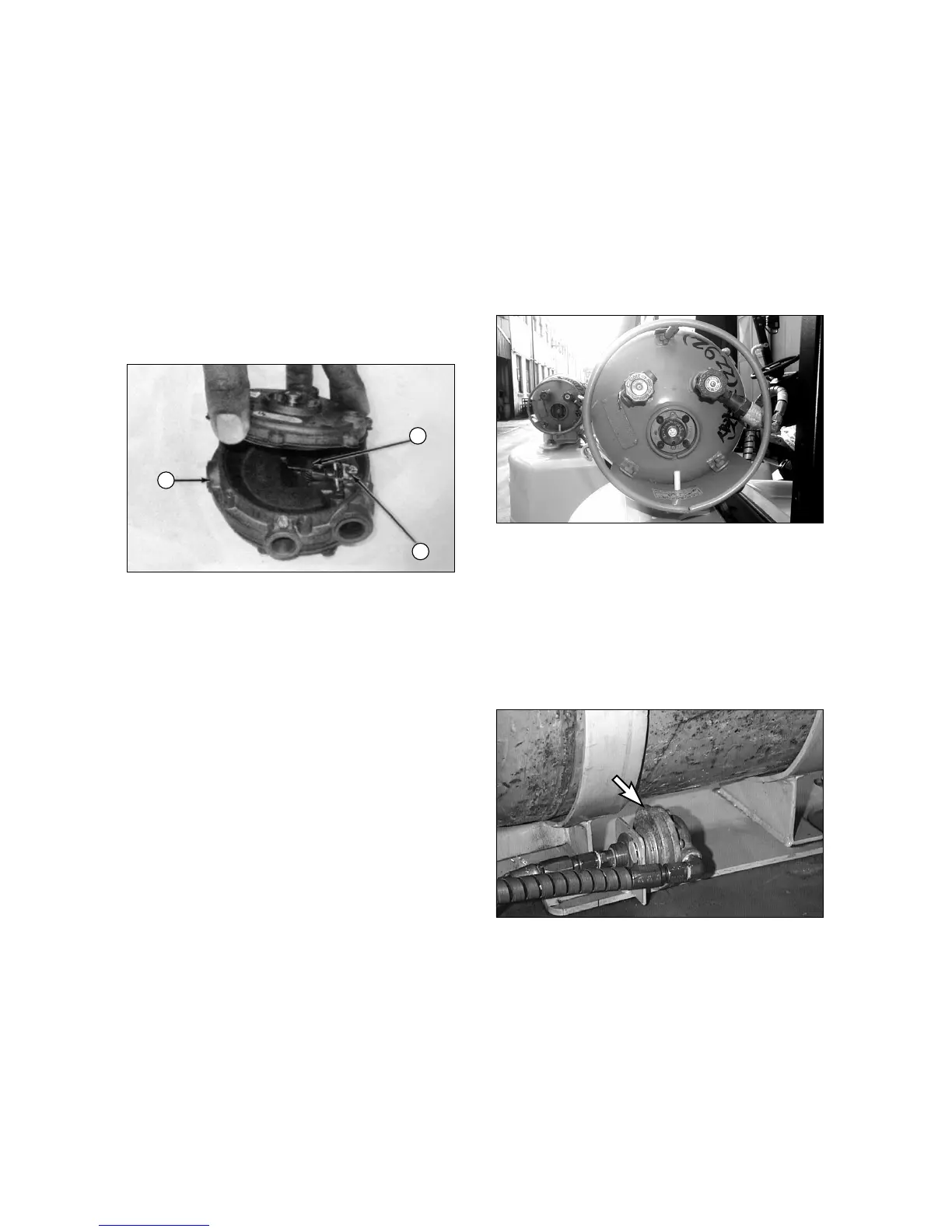
LP Relief Valve
Relief Valve
When the pressure in the LP fuel system gets too high,
the relief valve releases the pressure to the
atmosphere. The action of the relief valve prevents
damage to the fuel lines and other components of the
fuel system. The position of the valve is in a direction
that the fuel will not get on the operator when the valve is
activated.
 Loading...