- 86 -
LP Engine G430(3.0L) LP Fuel System (Low Emission Version)
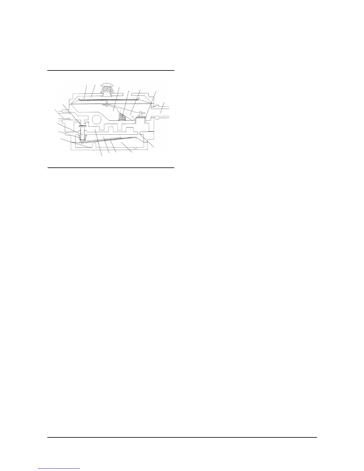
Pressure Regulator Theory of Operation
1. Fuel inlet
2. Primary valve
3. Primary spring
4. Primary heat exchanger chamber
5. Pressure transfer port
6. Primary diaphragm chamber
7. Secondary valve
8. Secondary spring
9. Primary diaphragm
10. Primary pivot
11. Primary pin
12. Coolant passage
13. Fuel outlet
14. Secondary vacuum chamber
15. Secondary diaphragm
16. Secondary atmospheric vent chamber
17. Secondary lever
18. Primary atmospheric chamber
Propane liquid, at tank pressure, enters the
regulator through the fuel inlet port (1). Propane
liquid then flows through the primary valve (2),
which is held normally open by the primary
spring(s) (3), and into the primary/heat exchanger
chamber of the regulator (4). A small port (5)
connects the primary/heat exchanger chamber and
the primary diaphragm chamber (6). The secondary
valve (7) at the outlet of the primary/heat exchanger
chamber (4) is held normally closed by the
secondary spring (8). Therefore the pressure in the
primary/heat exchanger chamber (4) and the
primary diaphragm chamber (6) begins to rise from
atmospheric pressure. When the pressure in the
primary/heat exchanger chamber (4) and primary
diaphragm chamber (6) reaches 1.5 psi (10.34kpa)
it causes a pressure/force imbalance across the
primary diaphragm (9) between the primary/heat
exchanger chamber (4) and the primary vent
chamber (18). This causes the primary diaphragm
and lever assembly (9) to pivot (10), against
primary spring (3) pressure, raising the primary
valve pin (11), closing off the primary valve (2).
Since the fuel pressure has been reduced from tank
pressure to 1.5 psi (10.34kpa) the liquid propane
vaporizes. As propane vaporizes it takes on heat
from the primary/heat exchanger chamber of the
regulator (4). This heat is replaced by engine
coolant, which is piped through a passage (12) in
the heat exchanger section of the regulator. Fuel
will not flow through the regulator to the engine until
a negative pressure signal is received from the
air/fuel mixer. When the engine is cranking or
running, a negative pressure signal generated by
the air/fuel mixer. This negative pressure signal
travels through the vapor fuel outlet (13) connection
between the air/fuel mixer and the regulator
secondary diaphragm chamber (14). The negative
pressure signal acts upon the lower side of the
secondary diaphragm (15) causing a
pressure/force imbalance across the secondary
diaphragm (15) between the secondary vacuum
chamber (14) and the secondary atmospheric vent
chamber (16). When the negative pressure signal
reaches negative 1.5 inches (38.10mm) of water
column the pressure/force imbalance overcomes
secondary spring (8) pressure and the secondary
diaphragm (15) moves toward the secondary
vacuum chamber (14). As the secondary
diaphragm moves it causes the secondary lever
(17) to pivot against the calibrated secondary spring
(8). As the secondary lever (17) pivots, it lifts the
secondary valve (7) off of its seat allowing
vaporized propane fuel to flow from the
primary/heat exchanger chamber (4), through the
secondary chamber (14), and on to the air/fuel
mixer. Since fuel has now exited the primary/heat
exchanger chamber (4) the pressure in the
chamber will drop allowing the primary valve (2) to
re-open. This creates a balanced condition
between the primary (4) and secondary (14)
chambers allowing for a constant flow of fuel to the
air/fuel mixer. While the flow of fuel is maintained at
a constant output pressure, due to the calibrated
secondary spring (8), the amount of fuel flowing will
vary depending on how far the secondary valve (7)
 Loading...