417102012_LMI02.doc - 63 - Rev. 9-07.08
6 Installation
6.1 Mechanical connection
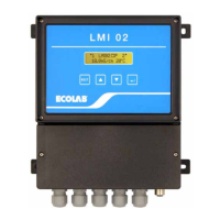
6.1.1 Installation of conductivity measuring and control instrument LMI 02
The conductivity measuring and control instrument LMI 02 is designed as a wall-mounted
instrument and is fixed in place with 4 screws.
6.1.2 Pipe installation (flow-through fitting)
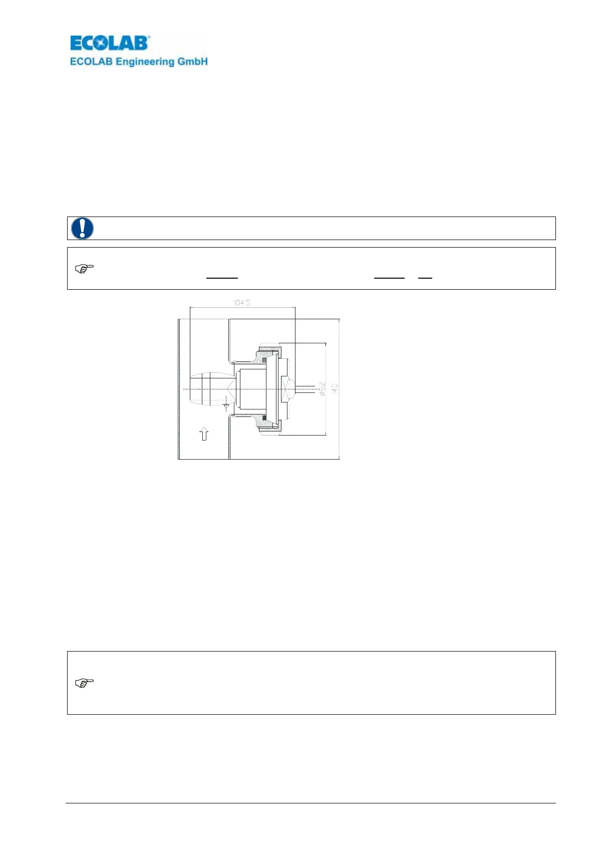
WARNING
The cross hole of the Measuring head must lie parallel to the tubular axle i.e. in the flow
direction of the medium.
NOTE
Deviations can lead to falsification of measuring values (eddy). The fitting position can be
controlled by marking arrows on the adapter of the Measuring head. The preferred set-up
would be vertical piping with flow direction from bottom to top.
The distance between the sensor and instrument should not exceed 20 m.
fig 6.1
Installation
Item no. for conductivity probe 0.2m in PEEK
with PVDF adapter: 287604
Item no. for conductivity probe 0.2m in PP
with PP adapter: 287622
Item no. for flow-through fitting 287507
Fix the
conductivity probe in the flow-through fitting and tighten with a coupling ring.
Pipe connection:
Type: Flow-through fitting (DIN 11851)
Material: 1.4301
Diameter: DN 50
Conductivity probe connection:
Type: Milk pipe fitting (DIN 11851)
Material: PEEK or PP
Diameter: DN 50
6.1.3 Tank wall installation
NOTE
The installation location must be selected so that sufficiently thorough mixing is ensured
in the area of the conductivity probe, and it must be at a considerably lower level than the
minimum level of the detergent solution even during running circulation. The transverse
borehole of the conductivity probe must be set up vertically or at an angle of up to max.
45°. The distance between the conductivity probe and instrument should be no more than
20 m.
 Loading...