REPLACING PARTS 57
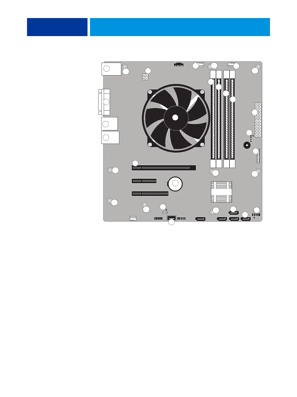
FIGURE 23: Motherboard
Key
1 Network port
2 Monitor
3 Type A USB ports
4 Crossover Ethernet port/USB
ports (x2)
5 CPU power (J18)
6 CPU cooling assembly
7 Printer interface board (PCI-E
X16)
8 Battery (XBT1)
9 UIB cable (J27)
10 DIMM0 (A1)
11 DIMM1 (A0)
12 DIMM2 (B1)
13 DIMM3 (B0)
14 CPU fan power (J16)
15 Front panel fan (J20)
16 Speaker (J83)
17 Motherboard power (ATX24P_1)
18 Front panel USB ports (J24)
19 Power and Reset (J15)
20 SATA_6G_0, DVD drive data
connection
21 SATA_6G_1, Hard disk drive data
connection
22 Clear CMOS Jumper (J4)
MH—Mounting holes
NOTE: Arrows indicate positions for
inserting cable and jumper
connections.
9
1
4
8
2
7
3
5
10
11
12
13
6
MH
MH
MH
MH
MH
MH
MH
MH
14
16
17
18
19
20
21
22
15
MH

 Loading...