REPLACING PARTS 81
TO REMOVE THE SWITCH BANK ASSEMBLY
1 Shut down, and then open the E-43A (see pages 43 and 44).
To remove the switch bank assembly, you must remove the left, right, and front panels.
2 Disconnect the following cables:
• Power and data combination cable from the back of the DVD drive
• Power and reset button cables from motherboard connector J15
• Speaker cable from motherboard connector J83
• Front panel USB port cables from motherboard connectors J24
3 Remove the ferrite that is installed around the front panel USB port cables near the
motherboard.
Carefully pry open the latch on the side of the ferrite and remove the ferrite from the cables.
Set the ferrite aside so that you can replace it later.
4 Unharness the cables from the cable clamp(s) and tie-wraps inside the chassis.
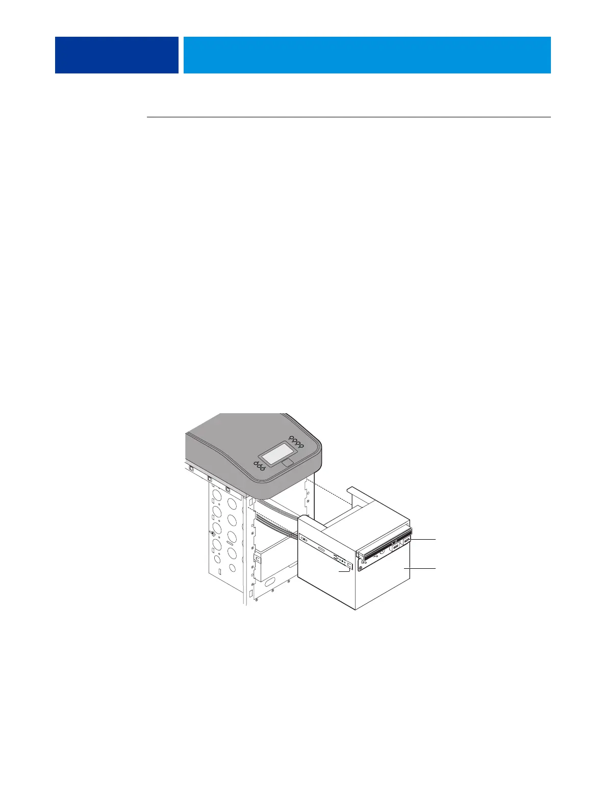
5 Remove the component sled from the chassis (see Figure 31 on page 80).
Press the guide latches on the sides of the component sled and carefully pull the sled out of its
slot in the front of the chassis.
FIGURE 32: Removing/replacing the component sled from the chassis
NOTE: Be careful not to damage the EMI gasket around the slot in the chassis. Guide the
cables out of the chassis as you remove the component sled to prevent them from catching or
tangling on internal parts.
Guide latch
(1 of 2)
Component sled
Switch bank assembly

 Loading...