REPLACING PARTS 69
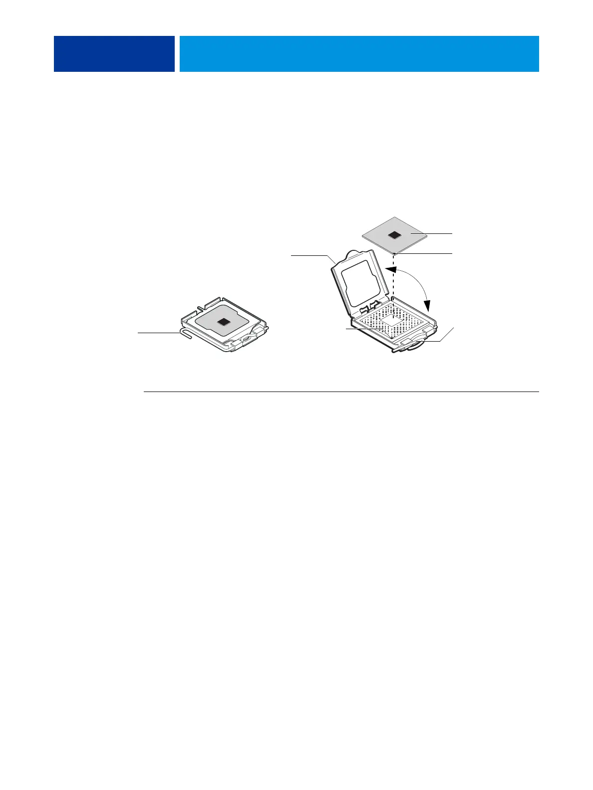
6 Place the CPU in the socket.
The CPU and the socket are keyed to ensure correct installation. The notches on the edges of
the CPU correspond with the two small posts inside the socket. Align the yellow triangle on
the CPU with the yellow triangle on the socket. Do not force the CPU.
7 Close the load plate.
8 Lower the socket lever and place it in the locked position under the retention post.
FIGURE 25: Removing/replacing the CPU
TO REPLACE THE CPU COOLING ASSEMBLY
NOTE: Before you install the cooling assembly, completely remove any thermal compound
residue on the surface of the CPU and the base of the heatsink, and then apply a fresh thermal
compound square to the base of the heatsink. When installing the thermal compound square,
make sure to remove the plastic backing on both sides of the square. Avoid creating any
bubbles or wrinkles on the square. Bubbles and wrinkles reduce the heat-transfer efficiency of
the cooling assembly.
1 Prepare the CPU cooling assembly for installation.
• Make sure that the motherboard is placed on a padded, static-free work surface.
• Apply a fresh thermal compound square, as described in the note above.
• Align the cooling assembly so that when it is installed, the fan cable easily reaches the CPU
fan power connector J16 on the motherboard.
2 Place the cooling assembly on the CPU.
• Make sure that the thermal pad on the underside of the heatsink is positioned on top of
the CPU.
Be sure to remove any protective material that may be covering the surface of the thermal
pad. Otherwise the CPU may overheat.
• Align the four screws with the four screw posts.
Tighten the screws. Partially tighten all the screws before tightening any one screw all the way.
Load plate open
CPU
Socket lever in
the open position
Socket lever in
the locked position
Yellow triangle
Yellow triangle

 Loading...