Calibration
March 2006
6-9
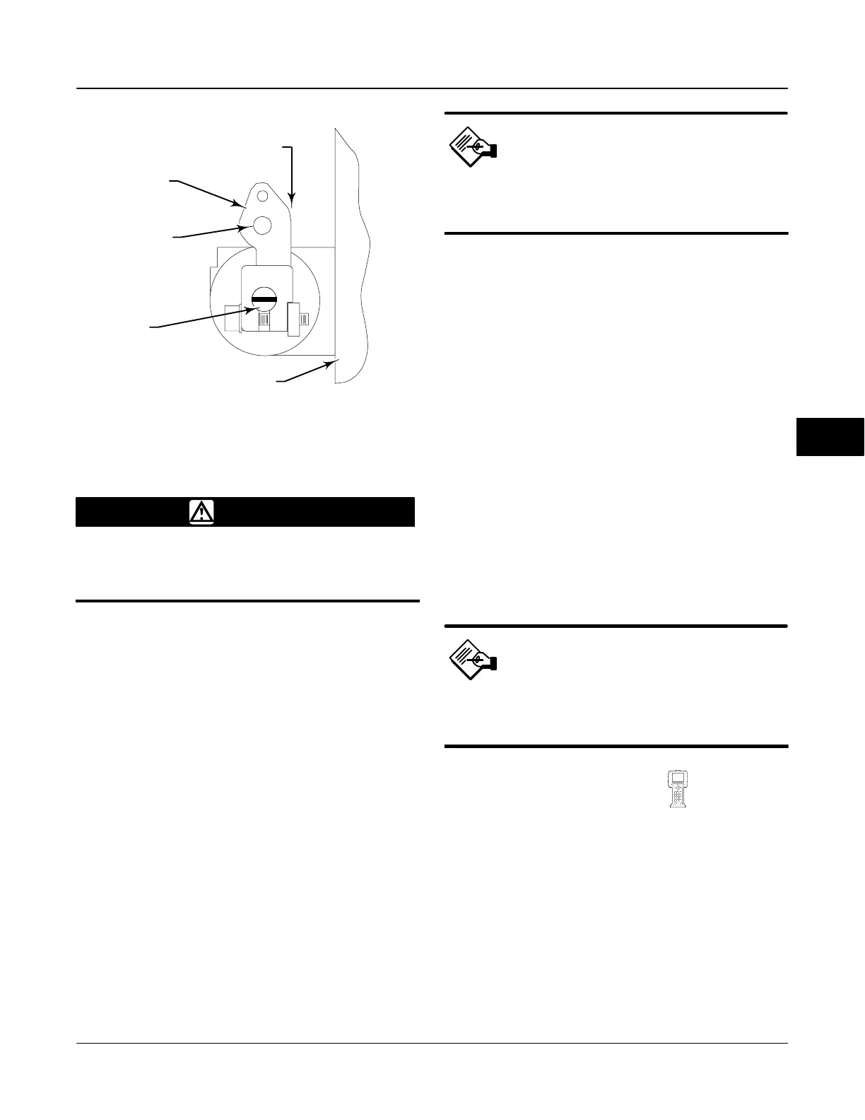
TRAVEL SENSOR
SHAFT
Figure 6-7. Type DVC6020f Travel Sensor Arm/Housing Back
Plane Alignment
ARM ASSEMBLY
BACK OF HOUSING
ARM ASSEMBLY PIN
BACK EDGE
OF ARM PARALLEL
W/BACK OF HOUSING
A7025 / IL
WARNING
Failure to remove air pressure may
cause personal injury or property
damage from bursting parts.
2. See figure 6-8 for parts identification. Disconnect
the bias spring (key 82) from the feedback arm
assembly (key 84) and the arm assembly (key 91).
Remove the mounting bracket (key 74) from the back
of the digital controller. Hold the arm assembly
(key 91) so that the arm assembly points toward the
terminal box and the arm is parallel to the back of the
housing, as shown in figure 6-7.
3. Loosen the screw that secures the arm assembly
to the travel sensor shaft. Position the arm assembly
so that the outer surface is flush with the end of the
travel sensor shaft.
4. Connect a fieldbus power source and the Field
Communicator to the instrument LOOP− and LOOP+
terminals.
5. Before beginning the travel sensor adjustment, set
the Transducer Block Mode to Manual and the
protection to None.
6. From the Calibrate menu, select Travel Sensor
Adjust. Follow the prompts on the Field Communicator
display to adjust the travel sensor counts to the value
listed in table 6-1.
Note
In the next step, be sure the arm
assembly outer surface remains flush
with the end of the travel sensor shaft.
7. While observing the travel sensor counts, tighten
the screw that secures the arm assembly to the travel
sensor shaft. Be sure the travel sensor counts remain
within the tolerances listed in table 6-1. Paint the
screw to discourage tampering with the connection.
8. Disconnect the Field Communicator and Fieldbus
power source from the instrument.
9. Apply lubricant (key 63) to the pin portion of the
arm assembly (key 91).
10. Replace the mounting bracket on the back of the
instrument and reconnect the bias spring between the
feedback arm assembly and the arm assembly on the
travel sensor shaft.
11. Install the digital valve controller on the actuator.
Pressure Sensor Calibration
There are three pressure sensors: Supply, Output A,
and Output B. Select the appropriate menu depending
upon which pressure sensor you are calibrating.
Note
The pressure sensors are calibrated at
the factory and should not require
calibration.
Supply Press Sensor Cal
(TB > Calibrate > Supply Press Sensor Cal)
For a Zero Only calibration, select Zero Only and
follow the prompts on the Field Communicator.
To calibrate for Zero and Span, connect an external
reference gauge to the output side of the supply
regulator. The gauge should be capable of measuring
maximum instrument supply pressure. Select Zero
and Span and follow the prompts on the Field
communicator.
When finished place the Transducer Block Mode in
Auto. Verify that the displayed pressure matches the
measured output pressure.
6
 Loading...


