DVC6000f Series
March 2006
2-20
Making Fieldbus Connections with
Twisted Shielded Pair
Refer to figures 11-1, 11-2, 11-4 and 11-6 for
identification of parts.
WARNING
Personal injury or property damage,
caused by fire or explosion, can result
from the discharge of static electricity.
Connect a 14 AWG (2.08 mm
2
) ground
strap between the digital valve
controller and earth ground when
flammable or hazardous gases are
present. Refer to national and local
codes and standards for grounding
requirements.
To avoid static discharge from the
plastic cover, do not rub or clean the
cover with solvents. Clean with a mild
detergent and water only.
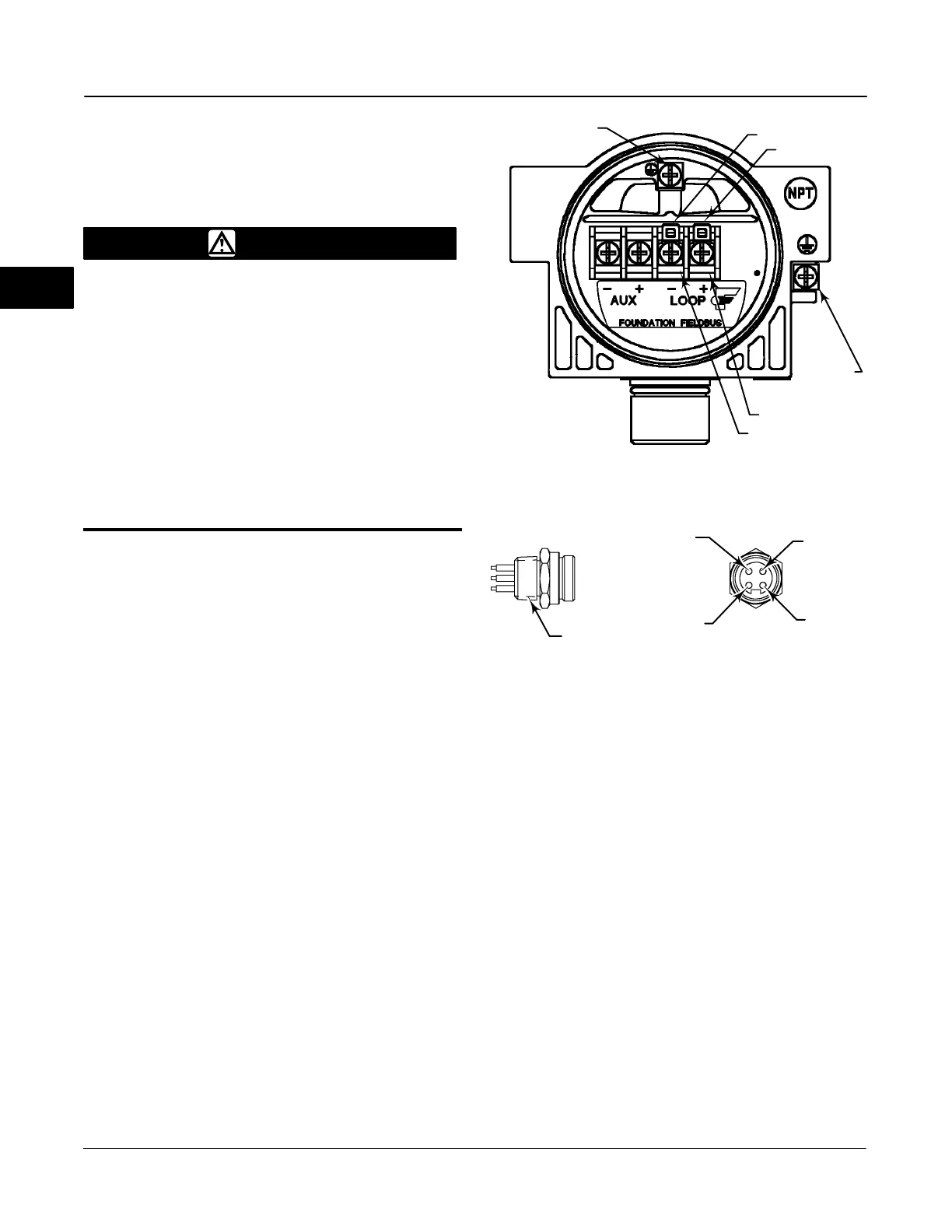
1. Remove the terminal box cap (key 4) from the
terminal box (key 3).
2. Bring the field wiring into the terminal box. When
applicable, install conduit using local and national
electrical codes which apply to the application.
3. The instrument is not polarity sensitive. Connect
one wire from the control system output card to one of
the LOOP screw terminals on the pwb/terminal strip
assembly in the terminal box shown in figure 2-17.
Connect the other wire from the control system output
card to the other LOOP screw terminal in the terminal
box.
4. As shown in figure 2-17, two ground terminals are
available for connecting a safety ground, earth ground,
or drain wire. The safety ground terminal is electrically
identical to the earth ground. Make connections to
these terminals following national and local codes and
plant standards.
5. Replace and hand tighten the terminal box cap on
the terminal box.
Figure 2-17. DVC6000f Series Digital Valve Controller
Terminal Box
38B6470-B
E0030-1 / IL
SAFETY GROUND
LOOP
LOOP
EARTH
GROUND
TALK
TALK
Figure 2-18. Quick Connect Connector
1/2-14 NPT
1
(BLUE)
2
(BROWN)
3
(NC)
4
(GREEN/YELLOW)
NOTES:
1. COLORS ARE WIRE COLORS.
2. NC=NO CONNECTION.
18B9424-A
Making Fieldbus Connections with the
Quick Connect Cable Entry
The DVC6000f is offered with a quick connect cable
entry option, shown in figure 2-18, for the
FOUNDATION fieldbus signal. The quick connect cable
entry provides an easier and more reliable interface to
fieldbus devices and support modules by providing a
standard connection.
2
 Loading...


