DVC6000f Series
March 2006
5-6
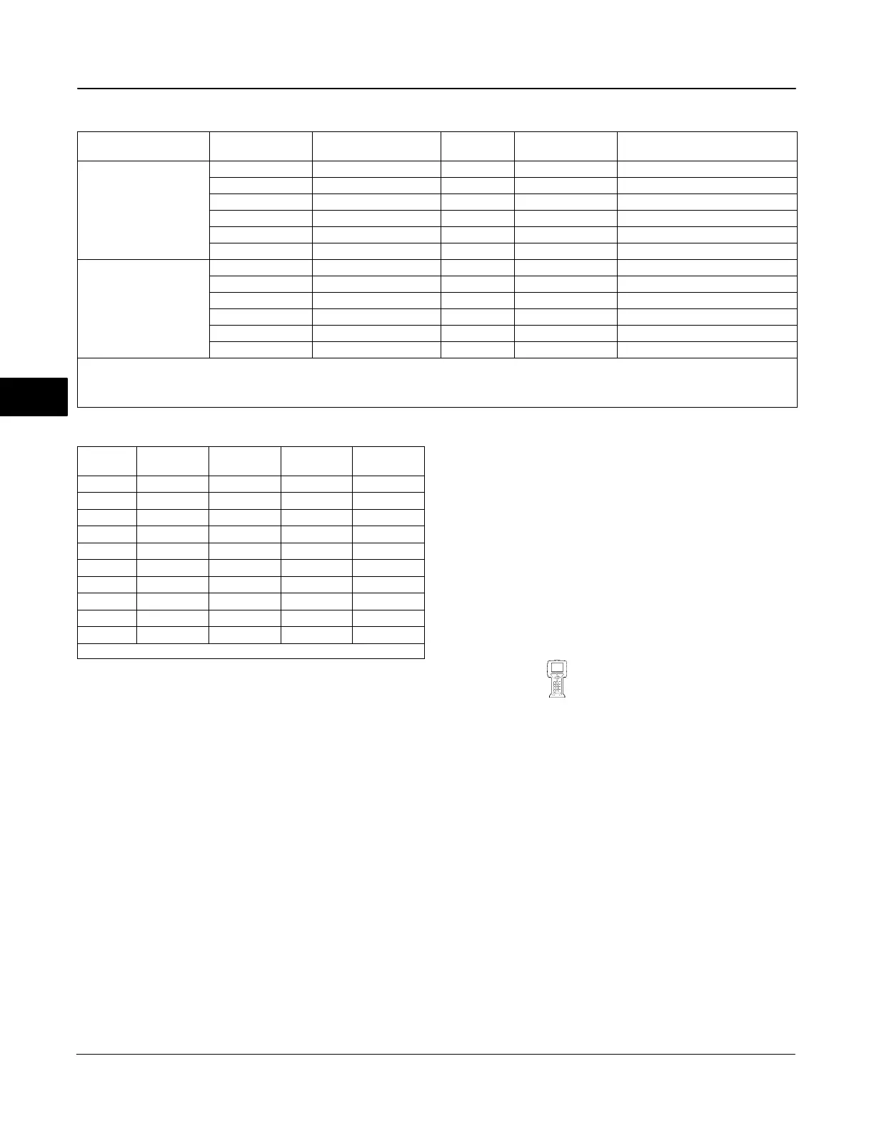
Table 5-1. Output Block PV Status
FEATURE_SEL
PW Alarms Set PV Status
Transducer Mode,
Actual
Active PlantWeb
Alarms
AO / DO
PV Status
(2)
AO / DO
PV Substatus
AO/DO PV
Limit Substatus
(1)
Enabled
OOS X Bad Device Failure
Constant
Man X Bad Non-specific
Constant
Auto Fail Uncertain Subnormal
See table 5-2
Auto Maint, no Fail Uncertain Non-specific
See table 5-2
Auto Advisory, no Fail, no Maint Good Advisory See table 5-2
Auto None Good Non-Specific See table 5-2
Not Enabled
OOS X Bad Device Failure
Constant
Man X Bad Non-Specific
Constant
Auto Fail Good Non-Specific
See table 5-2
Auto Maint, no Fail Good Non-Specific
See table 5-2
Auto Advisory, no Fail, no Maint Good Non-Specific See table 5-2
Auto None Good Non-Specific See table 5-2
NOTES:
X
= No Effect
1. PV limit substatus reflects only READBACK limit substatus. SP limit substatus reflects only out block rate limits.
2. Firmware Revision 1.1 and earlier will set AO/DO PV Status to Bad if Feedback Sensor has failed, ie; Travel Sensor Fail. However, if the Travel Sensor fails, and the instrument
falls back to pressure, PV Status will remain good.
Table 5-2. Limit Sub Status
Out
Block
Transducer
Mode
In Cutoff
Region
Rate
Limited
Limit
Sub-Status
AO, DO OOS X X Constant
AO, DO MAN X X Constant
AO AUTO High X High Limited
AO AUTO Low X Low Limited
AO AUTO X High High Limited
AO AUTO X Low Low Limited
AO AUTO None None Not Limited
DO AUTO X High High Limited
DO AUTO X Low Low Limited
DO AUTO X None Not Limited
NOTE: X = No Effect
Max Alerts Possible / Max Alerts Allow
To have the instrument report alerts without having the
host poll the alerts parameters, select the Reports
feature (see Feature Select).
Maximum Alerts Possible (MAX_NOTIFY [31])
indicates the maximum number of alert reports that
the device can send without getting a confirmation.
This limit is determined by the amount of memory
available for alert messages. The number can be set
lower, to control alert flooding, by adjusting Maximum
Alerts Allowed (LIM_NOTIFY [32]). If Max Alerts
Allowed is set to zero, no alerts are reported. Enter a
value between 0 and 3.
Acknowledge Option
Acknowledge Option (ACK_OPTION [38]) determines
if alarms associated with the block will be
automatically acknowledged.
Alarm Summary: Disabled
Alarm Summary (ALARM_SUM [37]) determines if the
Write Alarm (WRITE_ALM [40]) and Block Alarm
[BLOCK_ALM [36]) are disabled.
Block Alarm: Unacknowledged
The Block Alarm (BLOCK_ALM [36]) is used for all
configuration, hardware, connection failure or system
problems in the block.
Instrument
(RB > Setup > Instrument )
Strategy
Strategy (STRATEGY [3]) permits strategic grouping
of blocks so the operator can identify where the block
is located. The blocks may be grouped by plant area,
plant equipment, etc. Enter a value between 0 and
65535 in the Strategy field.
Tag Description
The Tag Description (TAG_DESC [2]) is used to
assign a unique 32 character description to each block
within the digital valve controller to describe the
intended application for the block.
Field Serial Number
The Field Serial Number (FIELD_SN [51]) is the serial
number of instrument assigned in field.
5
 Loading...


