Maintenance
March 2006
10-7
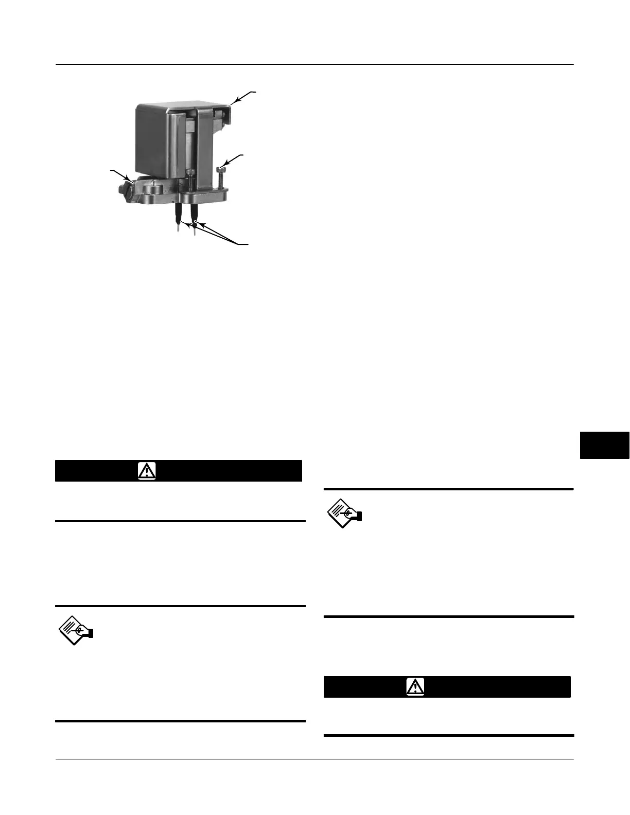
Figure 10-4. I/P Converter
SHROUD
(KEY 169)
W8071
BOOTS
(KEY 210)
SOCKET-HEAD
SCREWS (4)
(KEY 23)
I/P CONVERTER
(KEY 41)
4. Install the shroud (key 169) over the I/P converter
(key 41).
5. Install the four socket-head screws (key 23) and
evenly tighten them in a crisscross pattern to a final
torque of 1.6 Nm (14 lbfin).
6. After replacing the I/P converter, calibrate travel to
maintain accuracy specifications.
PWB (Printed Wiring Board) Assembly
WARNING
Refer to the Maintenance WARNING at
the beginning of this section.
Refer to figures 11-1 through 11-8 for key number
locations. The PWB assembly (key 50) is located on
the back of the module base assembly (key 2).
Note
If the PWB assembly submodule
is replaced, configure and
calibrate the digital valve
controller to maintain accuracy
specifications.
Removing the Printed Wiring Board
Assembly
1. Separate the module base from the housing by
performing the Removing the Module Base procedure.
2. Remove three screws (key 33).
3. Lift the PWB assembly (key 50) straight out of the
module base (key 2).
4. Ensure that the O-rings (key 40) remain in the
pressure sensor bosses on the module base assembly
(key 2) after the PWB assembly (key 50) has been
removed.
Replacing the PWB Assembly
1. Apply silicone lubricant to the pressure sensor
O-rings (key 40) and install them on the pressure
sensor bosses in the module base assembly.
2. Properly orient the PWB assembly (key 50) as you
install it into the module base. The two electrical leads
from the I/P converter (key 41) must guide into their
receptacles in the PWB assembly and the pressure
sensor bosses on the module base must fit into their
receptacles in the PWB assembly.
3. Push the PWB assembly (key 50) into its cavity in
the module base.
4. Install and tighten three screws (key 33) to a torque
of 1 Nm (10.1 lbfin).
5. Reassemble the module base to the housing by
performing the Replacing the Module Base procedure.
6. Setup and calibrate the digital valve controller.
Note
Calibration is required for either Travel
or Pressure Control after PWB
Assembly replacement.
Note that only one calibration is
needed, depending on control
selection.
Pneumatic Relay
WARNING
Refer to the Maintenance WARNING at
the beginning of this section.
10
 Loading...


