Maintenance
March 2006
10-15
Instrument Troubleshooting
What to Do First
When a problem occurs, check the following first:
Mounting
Is the feedback linkage connected correctly? See
the beginning of this section.
Utility Connections
Are pneumatic connections correct? Are there
any air leaks? See the Installation section.
Is the air supply pressure sufficient to drive the
valve?
Is the digital valve controller correctly connected
to the fieldbus? See the Installation section.
Is there power to the device? Is the terminal
voltage between 9 and 32 volts? See the Installation
section.
Is the segment terminated correctly? See host
system documentation.
Is the host system connected to the segment?
See host system documentation.
If communication or output difficulties are experienced
with the instrument, refer to the troubleshooting
information provided in table 10-2.
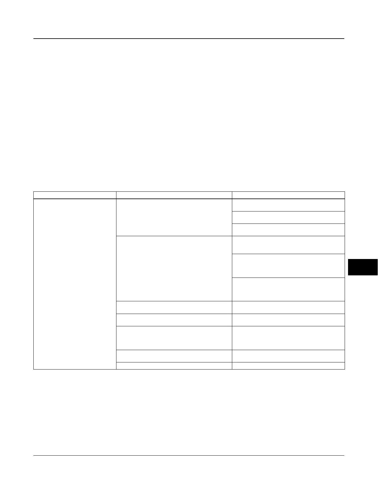
Table 10-2. Instrument Troubleshooting
Symptom Possible Cause Action
1. Instrument will not communicate. 1.a No power to device
1.a1 Ensure device is connected to the segment (see
host system documentation).
1.a2 Measure the terminal voltage. Terminal voltage
should be between 9 and 32 Vdc.
1.a3 Check to be sure device is drawing current.
There should be approximately 18mA.
1.b Internal device wiring problems.
1.b1 Verify connectors are plugged into the printed
wiring board correctly (see Printed Wiring Board
Assembly on page 10-7).
1.b2 Check continuity of cable between terminal box
and printed wiring board. If necessary, replace the
terminal box assembly (see Replacing the Terminal
Box on page 10-9).
1.b3 Check for damaged printed wiring board lands
and terminals. If necessary, replace the terminal box
assembly (see Replacing the Terminal Box on page
10-9).
1.c Incompatible network settings 1.c Change host parameters. Refer to host
documentation for procedure.
1.d Defective printed wiring board (PWB) assembly. 1.d Replace printed wiring board (see Replacing the
PWB Assembly on page 10-7).
1.e Defective terminal box. 1.e Check continuity from each screw terminal to the
corresponding PWB connector pin. If necessary,
replace the terminal box assembly (see Replacing the
Terminal Box on page 10-9).
1.f Defective Field Communicator or ValveLink
modem cable.
1.f If necessary, repair or replace cable.
1.g Fieldbus card defective or not compatible with PC. 1.g Replace Fieldbus card.
−Continued−
10
 Loading...


