DVC6000f Series
March 2006
10-8
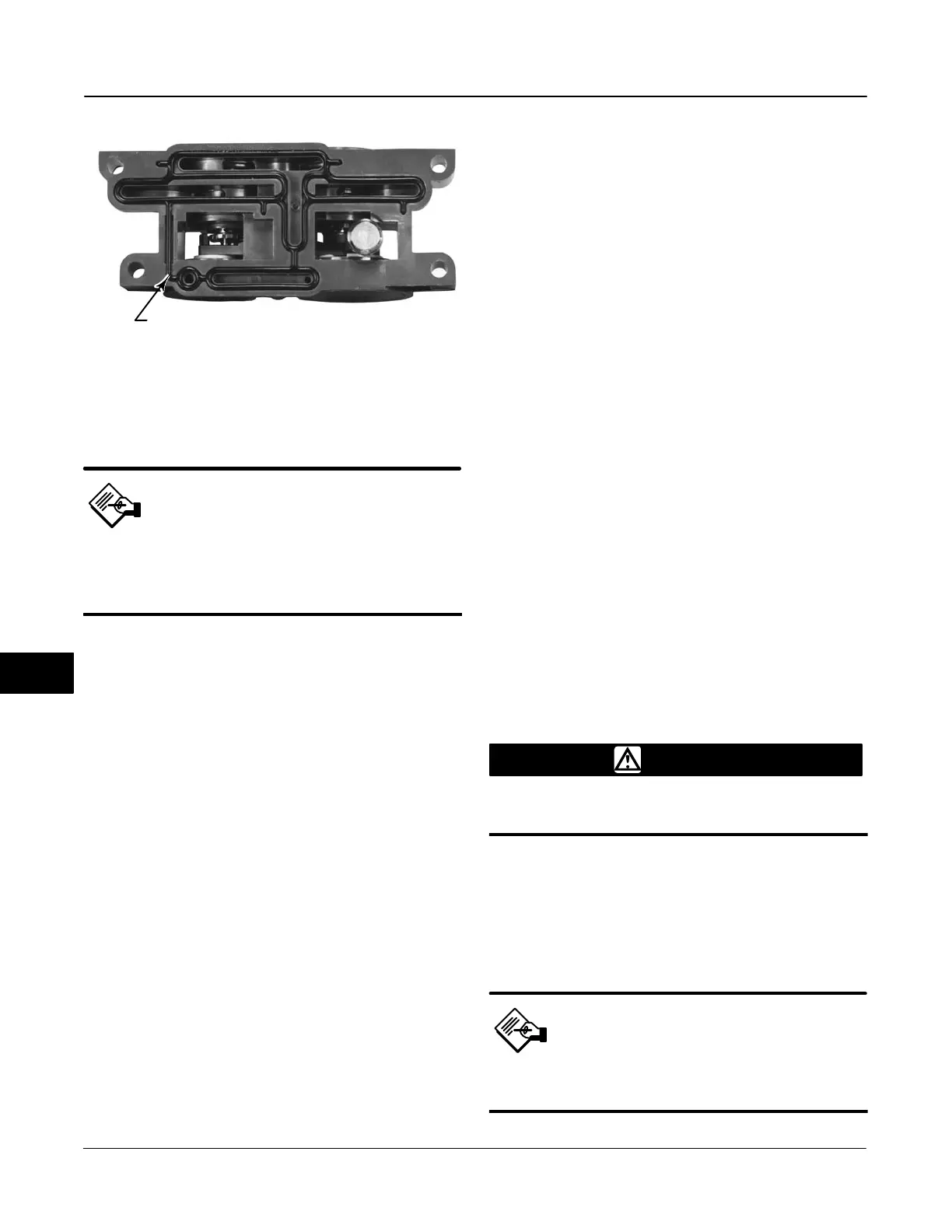
Figure 10-5. Pneumatic Relay Assembly
W8074
RELAY SEAL
Refer to figures 11-1 through 11-8 for key number
locations. The pneumatic relay (key 24) is located on
the front of the module base.
Note
After relay submodule replacement,
calibrate the digital valve controller
to maintain accuracy
specifications.
Removing the Pneumatic Relay
1. Loosen the four screws that attach the relay
(key 24) to the module base. These screws are
captive in the relay.
2. Remove the relay.
Replacing the Pneumatic Relay
1. Visually inspect the holes in the module base to
ensure they are clean and free of obstructions. If
cleaning is necessary, do not enlarge the holes.
2. Apply silicone lubricant to the relay seal and
position it in the grooves on the bottom of the relay as
shown in figure 10-5. Press small seal retaining tabs
into retaining slots to hold relay seal in place.
3. Position the relay (with shroud) on the module
base. Tighten the four screws, in a crisscross pattern,
to a final torque of 2 Nm (20.7 lbfin).
4. Using the Field Communicator, verify that the value
for the relay type parameter matches the relay type
installed.
5. After replacing the relay and verifying the relay
type, calibrate travel to maintain accuracy
specifications.
Gauges, Pipe Plugs, or Tire Valves
Depending on the options ordered, the DVC6000f
Series digital valve controller will be equipped with
either gauges (key 47), pipe plugs (key 66), or tire
valves (key 67). Single-acting direct instruments will
also have a screen (key 236, figure 11-8) These are
located on the top of the module base next to the
relay.
Perform the following procedure to replace the
gauges, tire valves, or pipe plugs. Refer to figures
11-1 through 11-8 for key number locations.
1. Remove the front cover (key 43).
2. Remove the gauge, pipe plug, or tire valve as
follows:
For gauges (key 47), the flats are on the gauge case.
Use a wrench on the flats of the gauge to remove the
gauge from the module base. To remove the supply
gauge, remove one of the output gauges.
For pipe plugs (key 66) and tire valves (key 67),
use a wrench to remove these from the module base.
3. Apply sealant (key 64) to the threads of the
replacement gauges, pipe plugs, or tire valves.
4. Using a wrench, screw the gauges, pipe plugs, or
tire valves into the module base.
Terminal Box
WARNING
Refer to the Maintenance WARNING at
the beginning of this section.
Refer to figures 11-1 through 11-8 for key number
locations.
The terminal box is located on the housing and
contains the terminal strip assembly for field wiring
connections.
Note
This procedure also applies to the
DVC6005f remote terminal box.
10
 Loading...


