Maintenance
March 2006
10-5
Replacing the Module Base
To replace the module base, for DVC6010f, DVC6020f
and DVC6030f digital valve controllers, perform the
following steps. Refer to figures 11-2, 11-4 and 11-6,
respectively, for key number locations. Refer to figure
10-2 for a view of the back of the PWB assembly
sub-module.
CAUTION
Inspect the guide surface on the
module and the corresponding seating
area in the housing before installing
the module base assembly. To avoid
affecting performance of the
instrument, these surfaces must be
free of dust, dirt, scratches, and
contamination.
Ensure the module base seal is in
good condition. Do not reuse a
damaged or worn seal.
1. Ensure the module base seal (key 237) is properly
installed in the housing (key 1). Ensure the O-ring (key
12) is in place on the module base assembly.
2. Connect the terminal box connector to the PWB
assembly (key 50). Orientation of the connector is
required.
3. Connect the travel sensor connector to the PWB
assembly (key 50). The connector is keyed, so proper
orientation is required.
4. Insert the module base (key 2) into the housing
(key 1).
5. Install three socket head screws (key 38) in the
module base into the housing. If not already installed,
press three retaining rings (key 154) into the module
base. Evenly tighten the screws in a crisscross pattern
to a final torque of 16 Nm (138 lbfin).
6. Attach the cover (key 43) to the module base
assembly.
7. For sliding-stem applications only, install the
protective shield onto the side of the replacement
module base assembly (see figures 2-1 and 2-2).
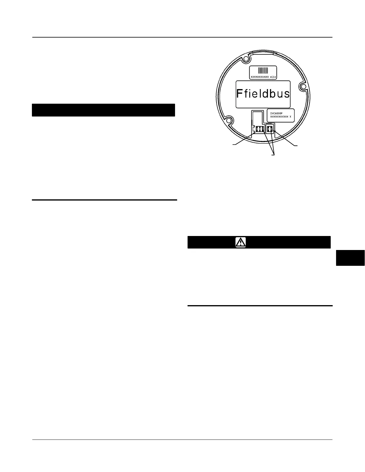
Figure 10-2. Back View of PWB Assembly Sub-Module
PINS REMOVED FOR CONNECTOR KEYING
TRAVEL SENSOR
CONNECTOR
TERMINAL BOX
CONNECTOR
GE04046
Submodule Maintenance
WARNING
To avoid personal injury or property
damage caused by fire or explosion,
remove power to the instrument
before replacing a submodule in an
area which contains a potentially
explosive atmosphere or has been
classified as hazardous.
The digital valve controller’s module base contains the
following submodules: I/P converter, PWB assembly,
and pneumatic relay. If problems occur, these
submodules may be removed from the module base
and replaced with new submodules. After replacing a
submodule, the module base is replaced in the
instrument and calibrated prior to returning to service.
10
 Loading...


