Installation
March 2006
2-15
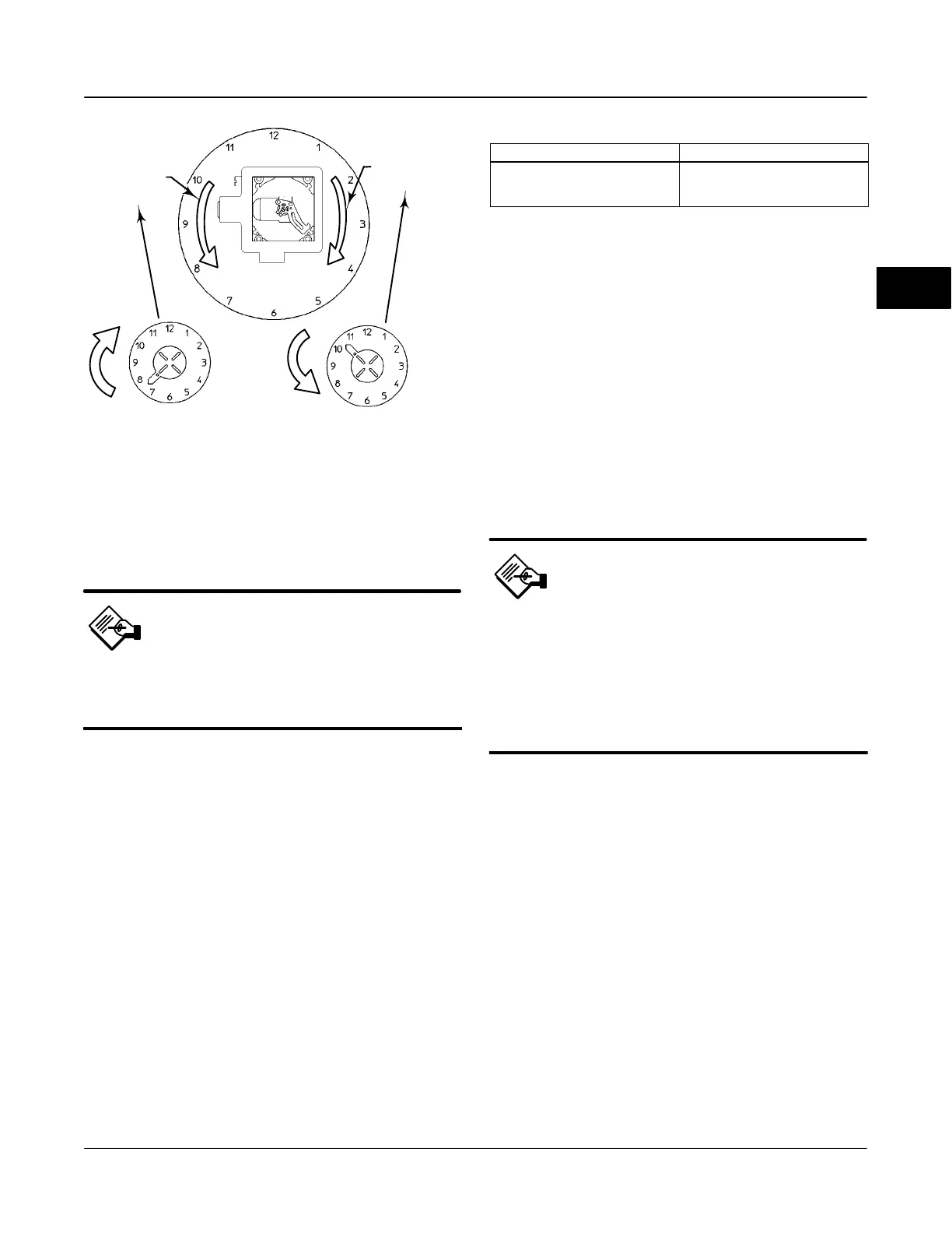
STARTING POSITION OF THE TRAVEL
INDICATOR ASSEMBLY IF INCREASING
PRESSURE FROM OUTPUT A DRIVES
THE INDICATOR CLOCKWISE. THE
POTENTIOMETER SHAFT WILL ROTATE
COUNTERCLOCKWISE AS VIEWED FROM
THE BACK OF THE INSTRUMENT.
STARTING POSITION OF THE TRAVEL
INDICATOR ASSEMBLY IF INCREASING
PRESSURE FROM OUTPUT A DRIVES
THE INDICATOR COUNTERCLOCKWISE.
THE POTENTIOMETER SHAFT WILL
ROTATE CLOCKWISE AS VIEWED
FROM THE BACK OF THE INSTRUMENT
Figure 2-13. Type DVC6035 Travel Indicator Installation
ACTUATOR SHAFT MOVEMENT
ACTUATOR SHAFT MOVEMENT
DVC6035
FEEDBACK ARM
MOVEMENT
DVC6035
FEEDBACK ARM
MOVEMENT
E0989
49B7988 / Doc
Note
While the housing differs on the
DVC6035 and the DVC6030f, feedback
parts are the same.
1. Isolate the control valve from the process line
pressure and release pressure from both sides of the
valve body. Shut off all pressure lines to the pneumatic
actuator, releasing all pressure from the actuator. Use
lock-out procedures to be sure that the above
measures stay in effect while working on the
equipment.
2. If necessary, remove the existing hub from the
actuator shaft.
3. If a positioner plate is required, attach the
positioner plate to the actuator as described in the
mounting kit instructions.
4. If required, attach the spacer to the actuator shaft.
Refer to figure 2-13. The travel indicator assembly can
have a starting position of 7:30 or 10:30. Determine
the desired starting position then proceed with the next
step. Considering the top of the remote travel sensor
as the 12 o’clock position, in the next step attach the
travel indicator, so that the pin is positioned as follows:
Table 2-1. Feedback Arm Locking Requirements
Digital Valve Controller Type Feedback Arm Alignment Hole
DVC6010f
DVC6020f
DVC6030f
B
Not Applicable
A
If increasing pressure from the digital valve
controller output A rotates the digital valve
controllers potentiometer shaft counterclockwise
(as viewed from the back of the instrument), mount
the travel indicator assembly such that the arrow is in
the 7:30 position, as shown in figures 2-9 and 2-13.
If increasing pressure from the digital valve
controller output A rotates the digital valve
controllers potentiometer shaft clockwise (as
viewed from the back of the instrument), mount the
travel indicator assembly such that the arrow is in the
10:30 position, as shown in figures 2-8 and 2-13.
Note
AMS ValveLink Software and the 375
Field Communicator use the
convention of clockwise (figure 2-8)
and counterclockwise (figure 2-9)
when viewing the potentiometer shaft
from the back of the FIELDVUE
instrument.
Mounting for Pressure Control
Mounting the digital valve controller for pressure
control does not require connecting the feedback
linkage. However, if the feedback linkage is not
connected, the feedback arm should be locked in
place. Insert the special stainless steel alignment pin
into either hole A or hole B of the feedback arm as
shown in table 2-1. To lock the feedback arm, insert
the alignment pin through hole A or B then screw the
alignment pin into the threaded hole in the side of the
housing.
The digital valve controller can be yoke-mounted or
casing-mounted on an actuator. DVC6000f Series
digital valve controllers setup for pressure control also
can be wall or pipestand mounted.
2
 Loading...


