Installation
March 2006
2-25
Simulate Enable Jumper
WARNING
Personal injury or property damage
caused by fire or explosion may occur
if this connection is attempted in a
potentially explosive atmosphere or in
an area that has been classified as
hazardous. Confirm that area
classification and atmosphere
conditions permit the safe removal of
the terminal box cap before
proceeding.
Install a jumper across the SIMULATE ENABLE
terminals to enable the instrument to accept a
simulate command. (These terminals are marked AUX
on the terminal board, see figure 2-17). With the
jumper in place and the simulate parameter in the AO
or DO block set to enabled, the transducer block
ignores the output of the AO or DO block. The
simulate value and status become the readback value
and status to the AO or DO block and the transducer
block is ignored. For more information on running
simulations, see the Detailed Setup / Blocks section of
this manual, the
FOUNDATION fieldbus specifications,
and the host documentation.
WARNING
Removing the jumper will disable the
simulate, which may cause the valve
to move. To avoid personal injury and
property damage caused by the
release of pressure or process fluid,
provide some temporary means of
control for the process.
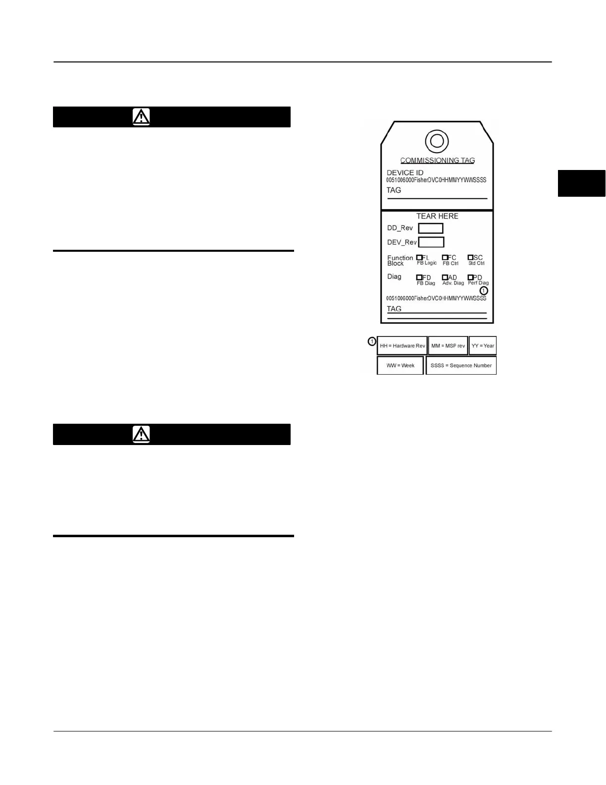
Commissioning Tag
The DVC6000f Series digital valve controller is
supplied with a removable paper commissioning tag,
shown in figure 2-22. This tag contains both the device
ID and a space to record the device’s tag number. The
device ID is a unique code that identifies a particular
device in the absence of a device tag. The device tag
is used as an operational identification for the device
and is usually defined by the piping and
instrumentation diagram (P&ID).
18B9406-D
Figure 2-22. Paper Commissioning Tag
When commissioning more than one device on a
fieldbus segment, identifying which device is at a
particular location can be tedious without tags. The
removable tag provided with the digital valve controller
can be used to link the device ID and the physical
installation location. The installer should note the
physical location in both places on the removable
commissioning tag and tear off the bottom portion.
This should be done for each device on the segment.
The bottom portion of the tags can be used for
commissioning the segment in the control system.
Prior to commissioning, the device ID is displayed by
the host system if no device tag is configured in the
digital valve controller electronics. Typically the
placeholder displays the device tag. The information
on the paper tag enables the engineer to match the
device ID to the correct placeholder.
As an ordering option, the factory can enter a device
tag into the digital valve controller electronics during
the manufacturing process. If this option is specified,
the device tag is displayed at the host system prior to
commissioning rather than the device ID. This makes
the job of commissioning the device easier.
2
 Loading...


