DVC6000f Series
March 2006
5-148
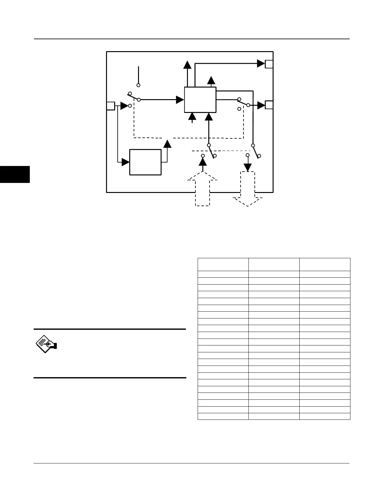
CAS_IN_D
IO_OPTS
RCAS_IN_D
SIMULATE_D
MODE
CHANNEL
TRANSDUCER
BLOCK
SP_D
PV_D
RCAS_OUT_D
OUT_D
BKCAL_OUT_D
READBACK_D
CONVERT AND
STATUS
CALCULATION
SHED MODE
Figure 5-29. Discrete Output Function Block Schematic
TRANSDUCER
BLOCK FEEDBACK
states used by the digital valve controller for the set
point.
To further customize the output, configure the
following supported I/O options: SP tracks PV in Man,
SP tracks PV in LO, SP Track retained target in Man
or LO, Fault State to Value, Use Fault State value on
restart, Target to Man if Fault State activated, and US
PV for BKCAL_OUT.
Note
You can configure the supported I/O
options in Out of Service mode only.
The SP_PV Track in Man option permits the set point
to track the process variable when the block is in
Manual mode. With this option enabled, the set point
(SP_D [8]) becomes a copy of the process variable
(PV_D [7]), and a manually-entered SP_D [8] value is
overwritten on the block’s next execution cycle. This
option can prevent a state change when transitioning
from Manual to Automatic mode. You can disable this
option in Manual or Out of Service mode only.
Table 5-69. Valve Set Point for Discrete State
Discrete State
Valve Set Point with
IO_OPTS Invert = 0
Valve Set Point with
IO_OPTS Invert = 1
0 Closed Open
1 Open Closed
5 5% Closed
10 10% Closed
15 15% Closed
20 20% Closed
25 25% Closed
30 30% Closed
35 35% Closed
40 40% Closed
45 45% Closed
50 50% Closed
55 55% Closed
60 60% Closed
65 65% Closed
70 70% Closed
75 75% Closed
80 80% Closed
85 85% Closed
90 90% Closed
95 95% Closed
100 Open Closed
The Invert option inverts the set point at SP_D [8]
before it is stored in OUT_D [9]. With this option
enabled, OUT_D [9] becomes an inverted copy of
SP_D [8] where non-zero values of SP_D [8] are
5
 Loading...


