DVC6000f Series
March 2006
A-8
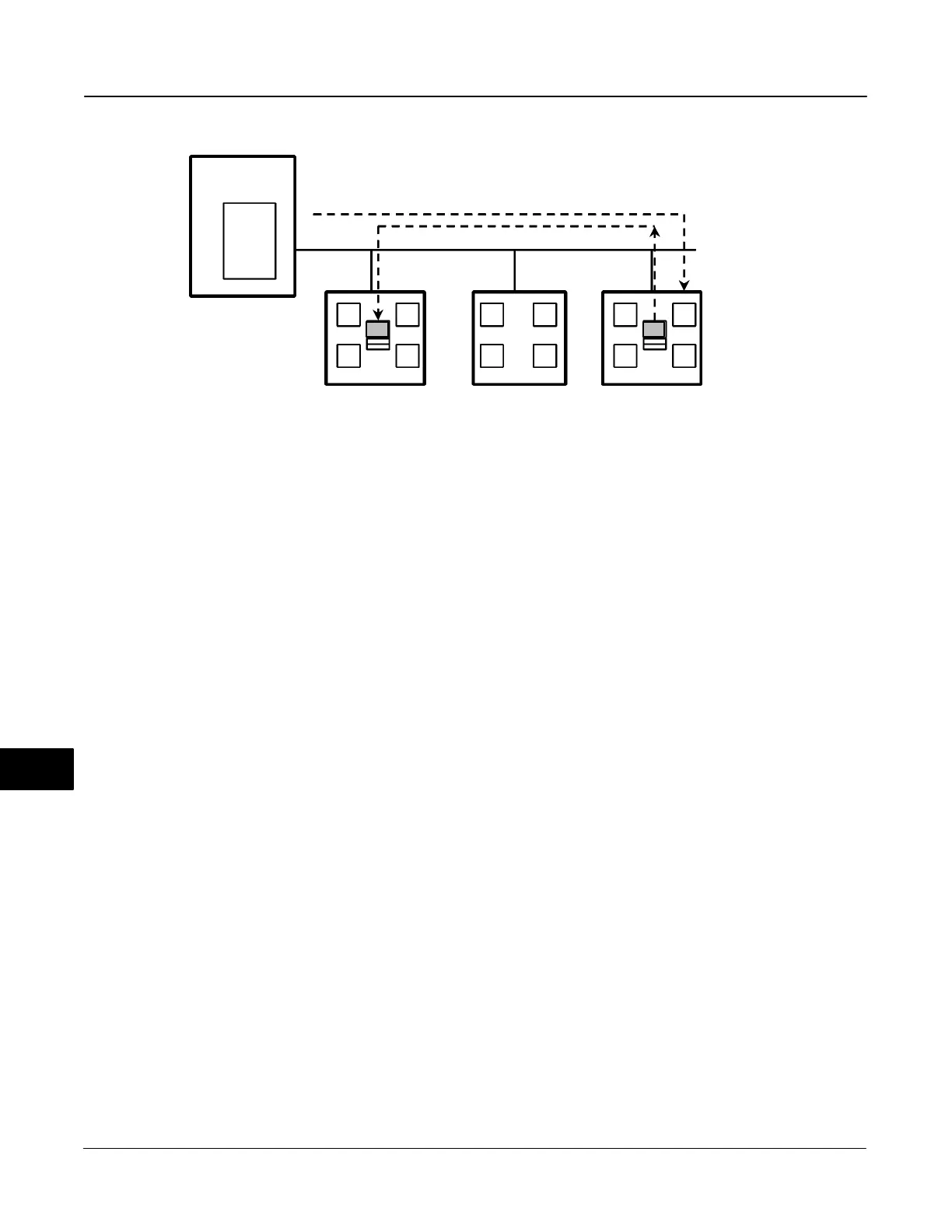
Figure A-5. Unscheduled Data Transfer
B2714-1 / IL
LAS
Device X Device Y Device Z
PT (Z)
LAS=Link Active Scheduler
P=Publisher
S=Subscriber
PT=Pass Token
M=Message
Schedule
X
Y
Z
B
PPPSS
S
CD
AAA
MM
Host System
Figure A-4 diagrams the method of scheduled data
transfer. Scheduled data transfers are typically used
for the regular cyclic transfer of process loop data
between devices on the fieldbus. Scheduled transfers
use publisher/subscriber type of reporting for data
transfer. The Link Active Scheduler maintains a list of
transmit times for all publishers in all devices that need
to be cyclically transmitted. When it is time for a
device to publish data, the LAS issues a Compel Data
(CD) message to the device. Upon receipt of the CD,
the device broadcasts or “publishes” the data to all
devices on the fieldbus. Any device that is configured
to receive the data is called a “subscriber”.
Client/Server: This type of communication is
used for request/ response exchanges between pairs
of devices, such as a set point change. Like Report
Distribution reporting, the transfers are queued,
unscheduled, and prioritized. Queued means the
messages are sent and received in the order
submitted for transmission, according to their priority,
without overwriting previous messages.
Unscheduled Transfers
Figure A-5 diagrams an unscheduled transfer.
Unscheduled transfers are used for things like
user-initiated changes, including set point changes,
mode changes, tuning changes, and upload/download.
Unscheduled transfers use either report distribution or
client/server type of reporting for transferring data.
All of the devices on the fieldbus are given a chance to
send unscheduled messages between transmissions
of scheduled data. The LAS grants permission to a
device to use the fieldbus by issuing a pass token (PT)
message to the device. When the device receives the
PT, it is allowed to send messages until it has finished
or until the “maximum token hold time” has expired,
whichever is the shorter time. The message may be
sent to a single destination or to multiple destinations.
Report Distribution: This type of
communication is used to broadcast and multicast
event and trend reports.
Function Block Scheduling
Figure A-6 shows an example of a link schedule. A
single iteration of the link-wide schedule is called the
macrocycle. When the system is configured and the
function blocks are linked, a master link-wide schedule
is created for the LAS. Each device maintains its
portion of the link-wide schedule, known as the
Function Block Schedule. The Function Block
Schedule indicates when the function blocks for the
device are to be executed. The scheduled execution
time for each function block is represented as an
offset from the beginning of the macrocycle start time.
To support synchronization of schedules, periodically
Link Scheduling (LS) time is distributed. The beginning
of the macrocycle represents a common starting time
for all Function Block schedules on a link and for the
LAS link-wide schedule. This permits function block
executions and their corresponding data transfers to
be synchronized in time.
A
 Loading...


