DVC6000f Series
March 2006
2-10
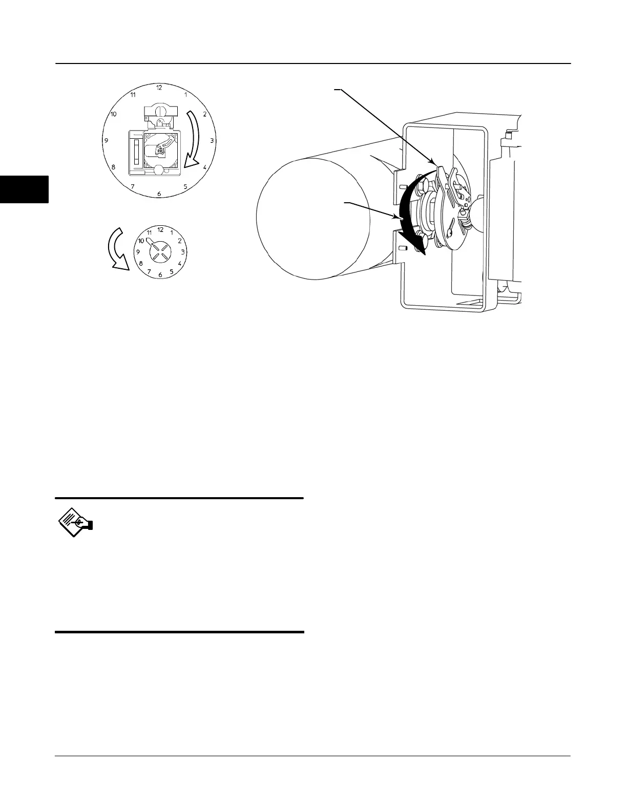
Figure 2-8. Explanation of Travel Indicator Starting Position and Movement, if Clockwise Orientation is Selected for
“Travel Sensor Motion” in AMS ValveLink
R
Software or the 375 Field Communicator
19B3879-A / DOC-1
STARTING POSITION OF THE ACTUATOR TRAVEL
INDICATOR ASSEMBLY IF INCREASING PRESSURE
FROM OUTPUT A DRIVES THE INDICATOR
COUNTERCLOCKWISE (THE POTENTIOMETER
SHAFT WILL ROTATE CLOCKWISE AS VIEWED
FROM THE BACK OF THE FIELDVUE INSTRUMENT)
STARTING POSITION OF TRAVEL
INDICATOR ASSEMBLY (DIGITAL
VALVE CONTROLLER OUTPUT A
AT 0 PSI. )
IN THIS POSITION, THE “B” HOLE
IN THE FEEDBACK ARM WILL BE
ALIGNED WITH THE REFERENCE
HOLE IN THE DIGITAL VALVE
CONTROLLERS HOUSING.
MOVEMENT OF TRAVEL
INDICATOR ASSEMBLY WITH
INCREASING PRESSURE FROM
OUTPUT A.
ACTUATOR SHAFT MOVEMENT
DVC6030f FEEDBACK
ARM MOVEMENT
E0989 / DOC
If increasing pressure from the digital valve
controller output A rotates the potentiometer shaft
counterclockwise (as viewed from the back of the
instrument), mount the travel indicator assembly such
that the arrow is in the 7:30 position, as shown in
figure 2-9.
Note
AMS ValveLink Software and the 375
Field Communicator use the
convention of clockwise (figure 2-8)
and counterclockwise (figure 2-9)
when viewing the potentiometer shaft
from the back of the FIELDVUE
instrument.
5. Attach the travel indicator to the shaft connector or
spacer as described in the mounting kit instructions.
6. Attach the mounting bracket to the digital valve
controller.
7. Position the digital valve controller so that the pin
on the travel indicator engages the slot in the feedback
arm and that the bias spring loads the pin as shown in
figure 2-10. Attach the digital valve controller to the
actuator or positioner plate.
8. If a travel indicator scale is included in the
mounting kit attach the scale as described in the
mounting kit instructions.
Guidelines for Mounting the Type
DVC6005f Base Unit
For remote-mounted digital valve controllers, the Type
DVC6005f base unit ships separately from the control
valve and does not include tubing, fittings or wiring.
See the instructions that come with the mounting kit
for detailed information on mounting the digital valve
controller to a specific actuator model.
For remote-mounted instruments, mount the Type
DVC6005f base unit on a 50.8 mm (2-inch) pipestand
or wall. The included bracket is used for either
mounting method.
Wall Mounting
Refer to figures 2-11 and 2-12. Drill two holes in the
wall using the dimensions shown in figure 2-11. Attach
the mounting bracket to the base unit using four
spacers and 25.4 mm (1-inch) 1/4-20 hex head
screws. Attach the base unit to the wall using suitable
screws or bolts.
2
 Loading...


