DVC6000f Series
March 2006
10-4
Table 10-1. Tools Required
Tool Size Use
Phillips Screwdriver
Hex key
Hex key
Hex key
Hex key
5 mm
1.5 mm
2.5 mm
5 mm
Relay, printed wiring board
assembly, and cover screws
Terminal box screw
Terminal box cover screw
I/P converter screws
Travel sensor screws
Hex key
Open-end wrench
Hex key
Open-end wrench
Hex key
6 mm
1/2-inch
9/64-inch
7/16-inch
3/16-inch
Module base screws
Connector Arm screw (DVC6010f)
Feedback arm screw
DVC6010f mounting bolts
DVC6020f mounting bolts
Removing the Module Base
WARNING
Refer to the Maintenance WARNING at
the beginning of this section.
To remove the module base for DVC6010f, DVC6020f
and DVC6030f digital valve controllers, perform the
following steps. Refer to figures 11-2, 11-4 and 11-6,
respectively, for key number locations.
WARNING
To avoid personal injury or equipment
damage from bursting of parts, turn
off the supply pressure to the digital
valve controller and bleed off any
excess supply pressure before
attempting to remove the module
base assembly from the housing.
1. For sliding-stem applications only, a protective
shield for the feedback linkage is attached to the side
of the module base assembly (see figures 2-1 and
2-2). Remove this shield and keep for reuse on the
replacement module. The replacement module will not
have this protective shield.
2. Unscrew the four captive screws in the cover
(key 43) and remove the cover from the module base
(key 2).
3. Using a 6 mm hex socket wrench, loosen the
three-socket head screws (key 38). These screws
are captive in the module base by retaining rings
(key 154).
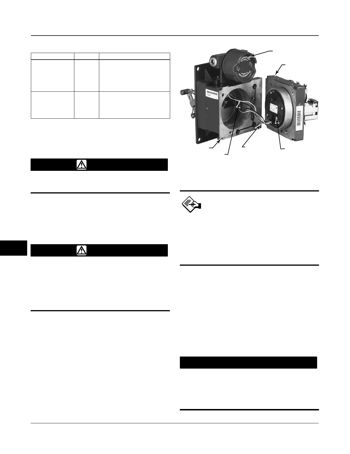
Figure 10-1. Printed Wiring Board Cable Connections
TERMINAL BOX
MODULE BASE
ASSEMBLY
PRINTED WIRING
BOARD ASSEMBLY
HOUSING
CABLE TO
TERMINAL BOX
W8073-FF
CABLE TO
TRAVEL SENSOR
Note
The module base is linked to the
housing by two cable
assemblies. Disconnect these
cable assemblies after you pull
the module base out of the
housing.
4. Pull the module base straight out of the housing
(key 1). Once clear of the housing, swing the module
base to the side of the housing to gain access to the
cable assemblies.
5. The digital valve controller has two cable
assemblies, shown in figure 10-1, which connect the
module base, via the printed wiring board assembly, to
the travel sensor and the terminal box. Disconnect
these cable assemblies from the printed wiring board
assembly on the back of the module base.
CAUTION
To avoid affecting performance of the
instrument, take care not to damage
the module base seal or guide surface.
Do not bump or damage the bare
connector pins on the PWB assembly.
10
 Loading...


