TIG modes
Safety
WARNING!
Danger from incorrect operation.
Possible serious injury and damage to property.
▶
Do not use the functions described here until you have read and completely under-
stood these Operating Instructions.
▶
Do not use the functions described here until you have fully read and understood all
of the Operating Instructions for the system components, in particular the safety
rules!
See the "The Setup menu" section for information on the settings, setting range and units
of measurement of the available welding parameters.
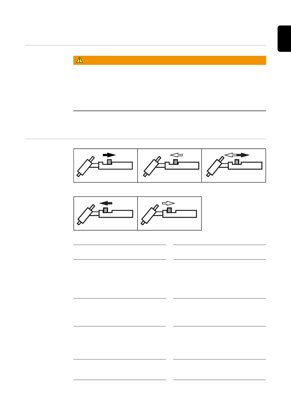
Symbols and
their explana-
tions
Pull back and hold the torch trigger / Release the torch trigger / Briefly pull back the torch trigger (< 0.5 s)
Push forward and hold the torch trigger / Release the torch trigger
GPr
Gas pre-flow time
SPt
Spot welding time
I
S
Starting-current phase: the temperature
is raised gently at low welding current,
so that the filler metal can be positioned
correctly
I
E
Final current phase: to prevent any local
overheating of the base material due to
heat build-up towards the end of weld-
ing. This eliminates any risk of weld
seam drop-through.
t
up
Upslope phase: the starting current is
continuously increased until it reaches
the main current (welding current) I
1
t
down
Downslope phase: the welding current is
continuously lowered until it reaches the
end-crater current.
I
1
Main current phase (welding-current
phase): uniform thermal input into the
base material, whose temperature is
raised by the advancing heat
I
2
Reduced current phase: intermediate
lowering of the welding current in order
to prevent any local overheating of the
base material
G-H
Gas post-flow time at maximum welding
current
G-L
Gas post-flow time at minimum welding
current
45
EN
 Loading...