SPECIAL EQUIPMENT (OPTIONAL)
100 OI 248 (EN) REV6 /REV0
12.1.3 Test condition
The shut-off valve Q1 is closed, the gas compartments (G1) and
(G2) are disconnected from each other.
The density monitor P1 monitors only the gas pressure in the volu-
me G2, but not the gas pressure in the switchgear gas compart-
ments.
The actuation lever (H) is placed vertically.
The central fill coupling (X1) can be used to change the gas pressu-
re in the volume G2 and check the display as well as the switching
points of the density monitor without influencing the gas pressure in
the switchgear gas compartments.
For this, a suitable test facility (e.g. SF
6
-multi analyser by DILO)
must be used that collects the escaping gas.
In the test condition, the density monitor can be exchanged as well
without emitting any gas to the environment.
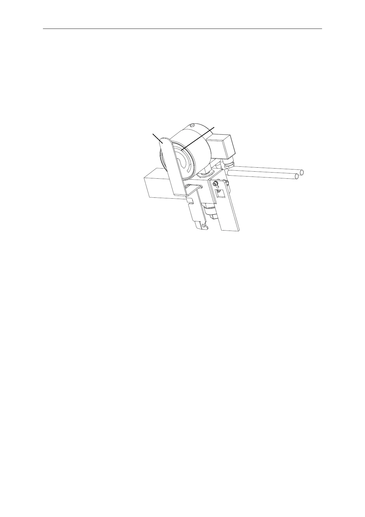
In the test condition, the dial of the density monitor is covered to the
greatest part.
When the lever is returned to the position "Operation", it will latch
on its own.
 Loading...


