INSTALLATION
REV6 /REV5 OI 248 (EN) 35
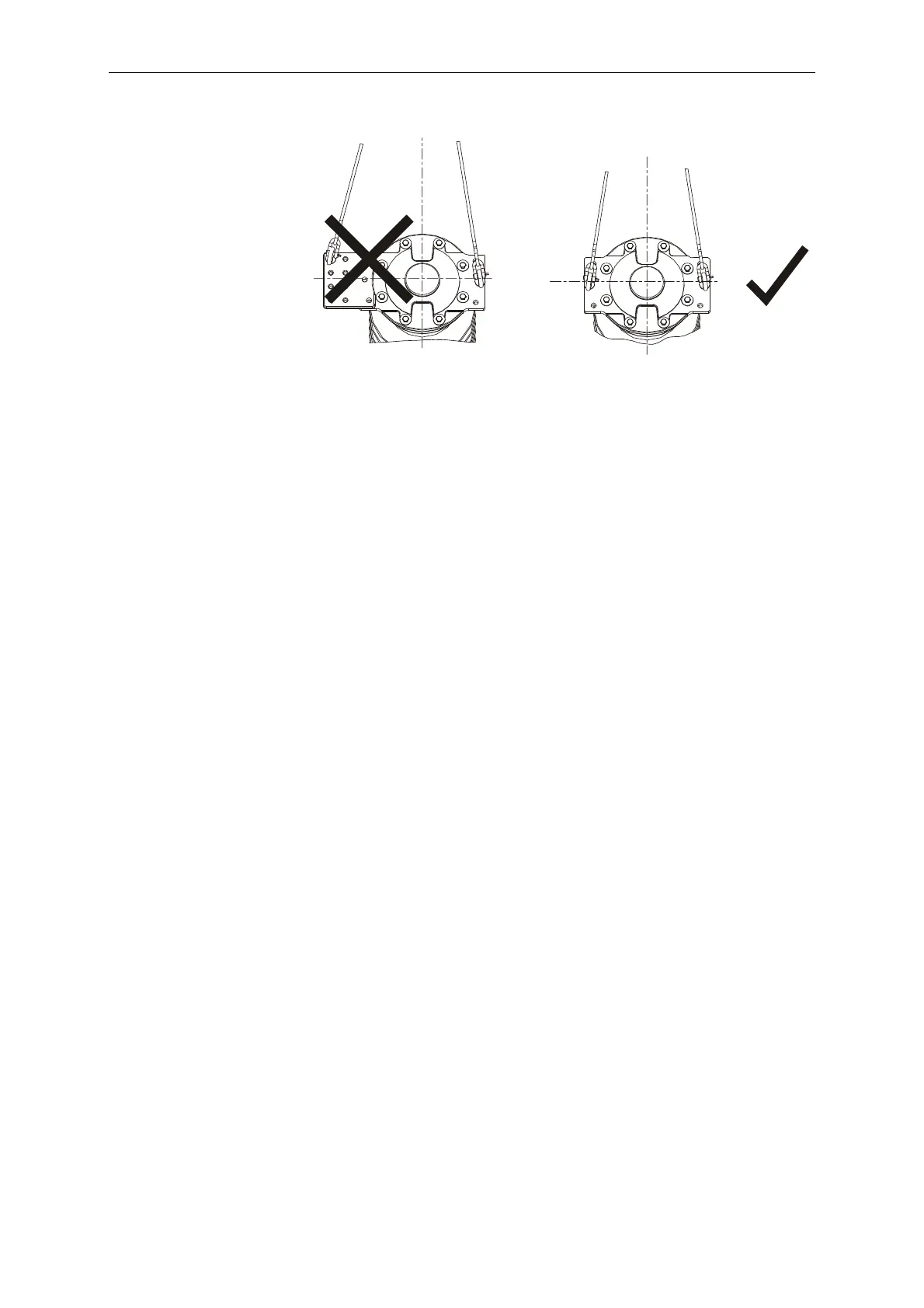
• Hoist the pole column to an upright position, carefully rolling it on
the rounded crankcase end.
6.8.2 Positioning the Pole Columns
• Find the proper pole position on the base frame (A, B or C as
viewed from the mechanism side; see illustration) and place the
pole column in this position above the base frame.
• Slowly lower the pole column. While lowering the pole column,
turn it slightly on its axis in order to avoid damage. Pay special
attention to the gas piping in the base frame.
• Lubricate the four pole column mounting bolts (4) as per L1 and
insert them from below. Screw on the nuts to the end of the
thread and then loosen them again one half revolution. Do not
tighten the nuts yet. The pole columns will be moved again on the
base frame during later alignment operations.
• Brace the tire lever (6) against the underside of the base frame
and push the pole column back until it hits the stop. This will allow
the linkage that will be installed later to be precisely aligned.
 Loading...


