INSTALLATION
38 OI 248 (EN) REV6 /REV5
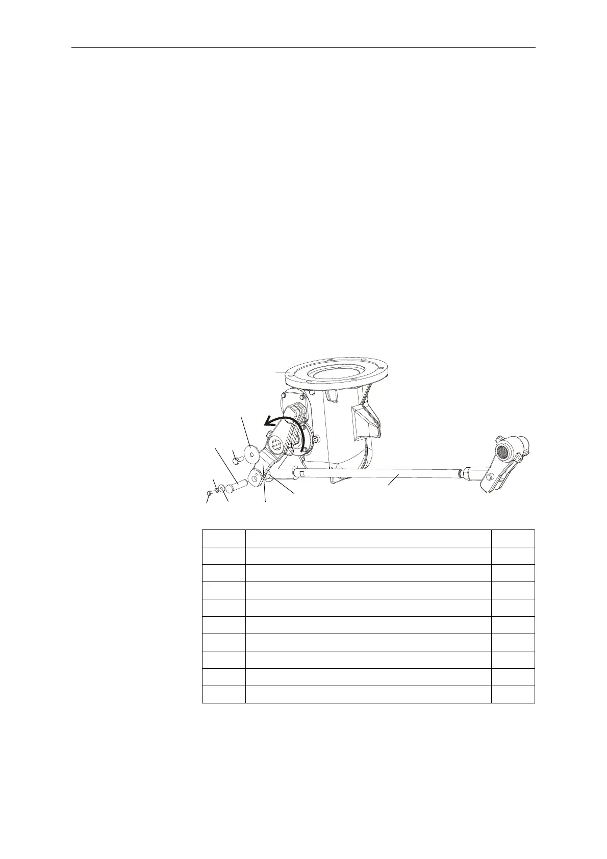
6.10.1 Connecting the Drive Rod to the Drive Lever
The drive rod and drive lever were already connected at the factory.
6.10.2 Connecting the Operating Mechanisms and Pole Columns
The following operations must be carried out in sequence for each
of the three pole columns.
• Lubricate the shaft of pole per L2.
• Fit lever (6) onto the shaft of pole (2).
• Apply locking adhesive S1 to the screw (9). Secure the lever with
the screw (9) and washer (10).
Tighten to a torque of 35 Nm.
• Insert the drive rod (5) into lever (6).
• Turn lever (6) in the direction of the arrow until the lever and the
shaft are in contact with one another. This reduces the clearance
between the lever and the shaft.
• Pull on the drive rod to reduce the clearance between the drive
shaft and drive lever.
• Check to make sure the holes in the lever and drive rod are
aligned.
2Pole 1x
5 Drive rod 1x
6 Lever 1x
9 Hexagon screw, M10x25 A2-70 1x
10 Washer, 50.5/11/3 1x
11 Locking sleeve 1x
12 Washer, 6 A2 1x
13 Hexagon screw, M6x16 A2-70 1x
14 Flanged coupling pin, 16x68 1x
15 Sleeve 1x
 Loading...


