INSTALLATION
REV6 /REV5 OI 248 (EN) 27
6.4.2 b Unpacking Pole Column with Porcelain Insulators
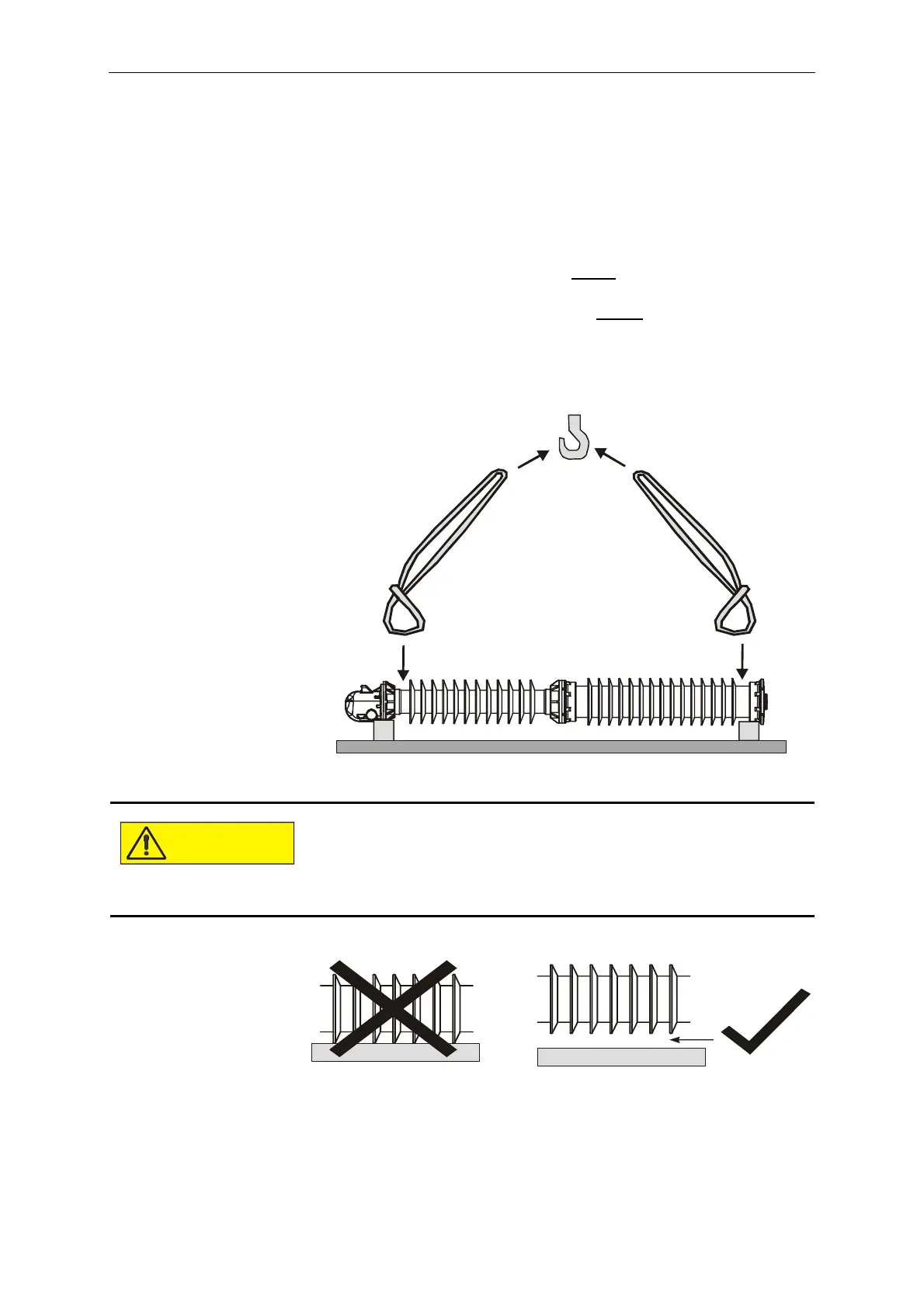
• Place two squared timbers on the ground as supports for the pole
column. The pole column must be deposited on the lowermost
and uppermost insulator flange, and the squared timbers must be
spaced accordingly. The insulator sheds must not come in
contact with the squared timbers or the ground, and the
dimensions of the squared timbers must be selected accordingly.
• Loop a sling around the insulator below
the sheds. Hook the other
end of the sling in the crane hook.
• Loop a sling around the insulator above
the sheds. Hook the
other end of the sling in the crane hook.
• Lift the pole column out of the packaging and lower it on to the
squared timbers.
Contact with the ground may damage the insulators.
Therefore:
- Select squared timbers of sufficient height, and position
them correctly in order to prevent the insulators from tou-
ching the ground.
 Loading...


