Home
GE
Circuit breakers
GL 313 F3/4031 P/VR
GE GL 313 F3/4031 P/VR User Manual
5
of 1
of 1 rating
140 pages
Give review
Manual
Specs
To Next Page
To Next Page
To Previous Page
To Previous Page
Loading...
R
ECONDITIONING
76
OI 248 (EN)
REV6
/REV6
10.1.2
Removing the Double Motion Syste
m
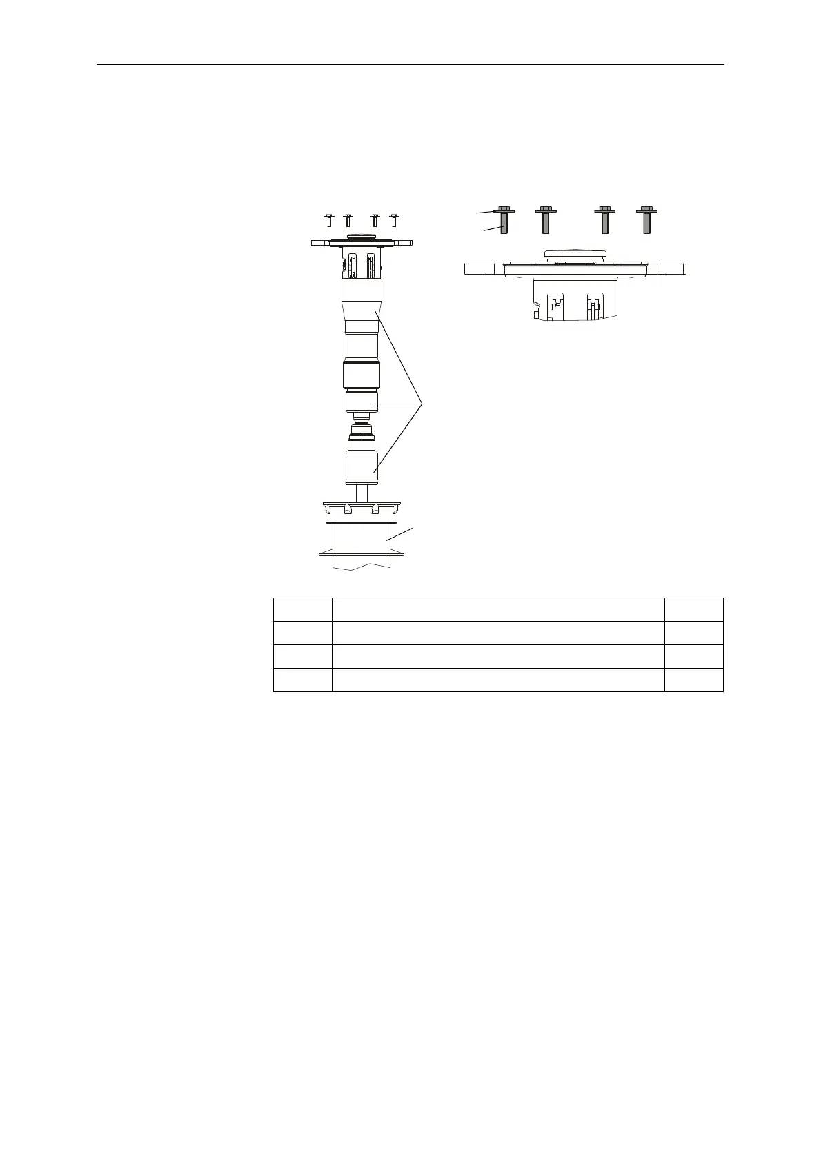
•
Remove eight screws (3) and washers (4) from the upper flange
of the chamber insulator (1).
•
Carefully remove the double
motion system (2).
1
Chamber insulator
1x
2
Double motion system
1x
3
Hexagon screw, M12x45 A2-70
8x
4
Washer, 12x40 A2
8x
2
1
4
3
BA-P-PS-2
75
77
Table of Contents
Table of Contents
3
Introduction
7
Safety
11
Safety Instructions
11
Handling Sulfur Hexafluoride
13
Safety Precautions When Handling SF6
13
Oxygen Displacement
13
Mechanical Handling
13
Frostbite
14
Safety Precautions When Handling Used SF6
15
Transport at the Installation Site
16
Components Supplied
17
Scope of Supply (Standard)
17
Scope of Supply (Optional)
18
Transport and Storage
19
Transport and Handling
19
Storage
20
Installation
21
Preparing for Installation
21
Documentation
21
Checklist
21
Materials and Equipment to be Provided by Customer
24
Use of Auxiliary Materials and Supplies
24
Unpacking the Transport Units
24
Base Frame and Operating Mechanisms
24
Pole Column
25
Unpacking Pole Column with Composite Insulators
26
Unpacking Pole Column with Porcelain Insulators
27
Preinstalling the Supports
30
Installing the Base Frame and Operating Mechanisms
31
Preparing the Operating Mechanisms
32
Removing the Transport Lock
32
Installing the Pole Columns
34
Erecting the Pole Columns
34
Positioning the Pole Columns
35
Aligning and Connecting the Pole Columns
37
Aligning and Connecting Pole Column B
37
Connecting the Drive Rod to the Drive Lever
38
Connecting the Operating Mechanisms and Pole Columns
38
Mounting the High Voltage Terminal Pads
40
Connecting the Cables
41
Earthing (Grounding) the Circuit Breaker
42
Commissioning
43
Density Monitor
43
Connecting the Cable
43
Checking the Operating Points of the Density Monitor
44
Filling the Pole Columns with Gas (Preparation)
46
Establish Gas Connections between Density Monitor and Pole Columns
47
Filling the Breaker with Gas
48
Checking the Anti-Condensation Heater
50
Connecting the Supply and Control Cables
50
Functional Testing
51
Test Operations
51
Measuring the Running Time of the Charging Motor
51
Measuring the Contact Resistance
52
Measuring the Operating Times
52
Checking Manual Operation
53
Manually Charging the Closing Spring
54
Checking the Anti-Pumping System
55
Check Synchronized Operation
55
Checking the Functional Lockout
55
Operations Counter
56
Final Tasks
56
Troubleshooting
57
Electrical Switching Commands Are Not Correctly Executed
57
Mechanism Reconditioning Procedures
58
Replacing the Charging Motor
58
Replacing the Closing and Opening Coil
59
Replacing the Operations Counter
60
Replacing the Motor Limit Switch And/Or the Auxiliary Switch
61
Replacing the Density Monitor
63
Austausch einer Gasverbindung
65
Inspection and Maintenance
67
Ordering Accessories and Replacement Parts
69
Inspection
69
Visual Inspection
69
Anti-Condensation Heater
69
Checking Gas Pressure
69
Maintenance
70
Checking the Cable Connections
70
Checking the Connecting Linkage
70
Checking the Control Circuits
70
Checking the Gas Quality
71
Checking the Contact Resistance
71
Checking the Operating Times
71
Checking the Threaded Connections
71
Reconditioning
73
Reconditioning the Interrupter Chamber
74
Disconnecting the Interrupter Chamber from the Post Insulator
74
Removing the Double Motion System
76
Removing the Guide Shaft
77
Disconnecting the Making and Breaking Units
78
Reconditioning the Movable Contact System
78
Reconditioning the Fixed Contact
79
Lubricating the Interrupter Unit
79
Connecting the Making and Breaking Units
80
Mounting the Guide Shaft
82
Reconditioning the Holder
83
Installing the Double Motion System
84
Adjusting the Double Motion System
86
Connecting the Interrupter Chamber to the Post Insulator
87
Replacing the Adsorption Filter
89
Final Operations
90
Disassembling the Post Insulator and Crankcase
90
Disassembling the Opening Springs
91
Disassembling the Crankcase
92
End-Of-Life Management
95
Special Equipment (Optional)
97
Easycheck Density Monitor Unit
97
Functional Description
98
Operating Condition
99
Test Condition
100
Flexlink-Gas Connection
101
Setup of the Flexlink-Gas Connction
101
If Flexlink Gas Piping Is Already Installed
102
Flexlink Gas Piping Still Needs to be Installed
103
Exchange of Flexlink Gas Connections
104
A1 Description of the Equipment
107
A1.1 Purpose
107
A1.2 Main Components
107
A1.3 Operation
107
A2 Tools and Auxiliary Equipment
109
A2.1 Customer-Supplied Materials and Equipment for Installation
109
And Commissioning
109
A2.2 Materials
109
A2.3 Hoisting and Climbing or Lifting Equipment
109
A2.4 Tools, Test Equipment and Auxiliary Equipment
109
A2.4.1 Tool Recommendations
110
A2.5 Greases for Installation, Commissioning and Maintenance
113
A2.6 Locking Adhesives for Installation, Commissioning and Maintenance
114
A2.7 Measuring Devices for Checking Gas Quality
114
A2.8 Tools for Reconditioning
115
A2.9 Auxiliary Materials and Supplies
116
A3 Replacement Parts and Accessories
117
A3.1 Servicing Equipment
118
A3.2 Replacement of Arcing Contacts
119
A3.3 Replacement Parts for Installation Work on Post Insulator and Crankcase
119
A4 Handling Used Sulfur Hexafluoride
121
A5 Technical Description
123
Technical Data: Circuit Breaker Type GL 310-GL 312
123
Technical Data: Circuit Breaker Type GL 313
124
A5.3 Technical Data: Spring Operating Mechanism
125
A6 Slow Operation for Maintenance Purposes
127
5
Based on 1 rating
Ask a question
Give review
Questions and Answers:
Need help?
Do you have a question about the GE GL 313 F3/4031 P/VR and is the answer not in the manual?
Ask a question
GE GL 313 F3/4031 P/VR Specifications
General
Brand
GE
Model
GL 313 F3/4031 P/VR
Category
Circuit breakers
Language
English
Related product manuals
GE GL 310 F3/4031 P/VR
140 pages
GE GL 311 F3/4031 P/VE
146 pages
GE GL 310 F1/4031 P/VR
151 pages
GE GL 312 F1/4031 P/VR
151 pages
GE GE-200A
2 pages
GE GEH-6285C
118 pages
GE Gerapid 2607
54 pages
GE EntelliGuard G
43 pages
GE PowerVac GEK-86132G
44 pages
GE PowerVac GEK-86132F
40 pages
GE POWER/VAC GEK 86132A
45 pages
GE AK-15
28 pages
 Loading...


