RECONDITIONING
REV6 /REV6 OI 248 (EN) 83
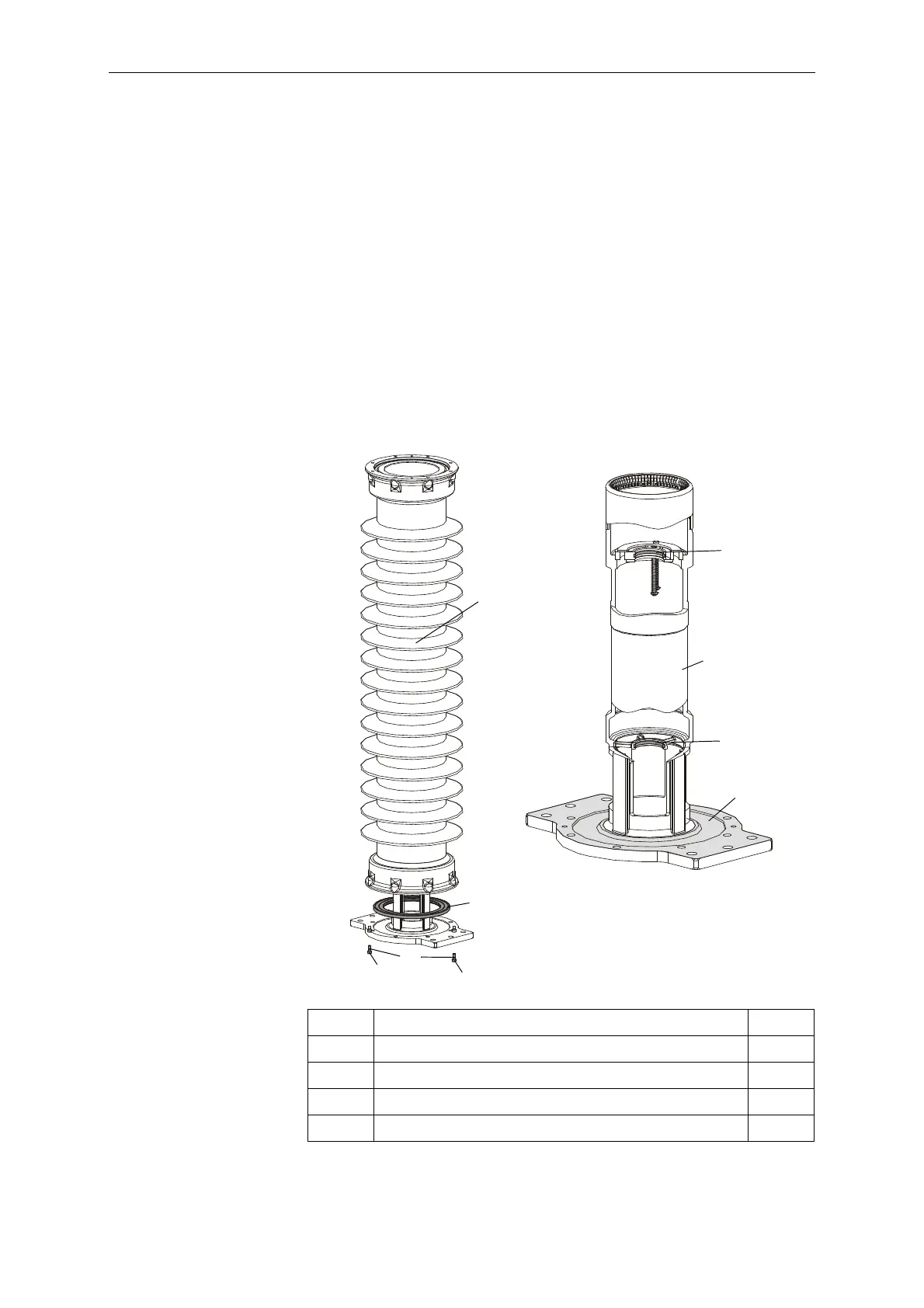
10.1.10 Reconditioning the Holder
• Attach lifting tackle to the upper flange of the chamber insulator.
• Loosen and remove two screws (17) on the lower flange of the
chamber insulator (1).
• Lift up the chamber insulator.
• Replace the two guide strips (18). The guide strips are located in
dovetail grooves. It is therefore necessary to overcome
mechanical resistance when replacing it.
• Clean the sealing and flange surfaces of the holder (16) and
grease them per lubrication specification L3.
• Replace the formed gasket (19).
• Lubricate two screws (17) per L1.
• Replace the chamber insulator and fasten it with two screws (17).
Tighten to a torque of 17Nm.
Fill the counterbores in the holder completely with grease per L3.
1 Chamber insulator 1x
16 Holder 1x
17 Socket head cap screw, M8x20 A-70 2x
18 Guide strip, 3x5x146 2x
19 Formed gasket 271 1x
 Loading...


