RECONDITIONING
78 OI 248 (EN) REV6 /REV6
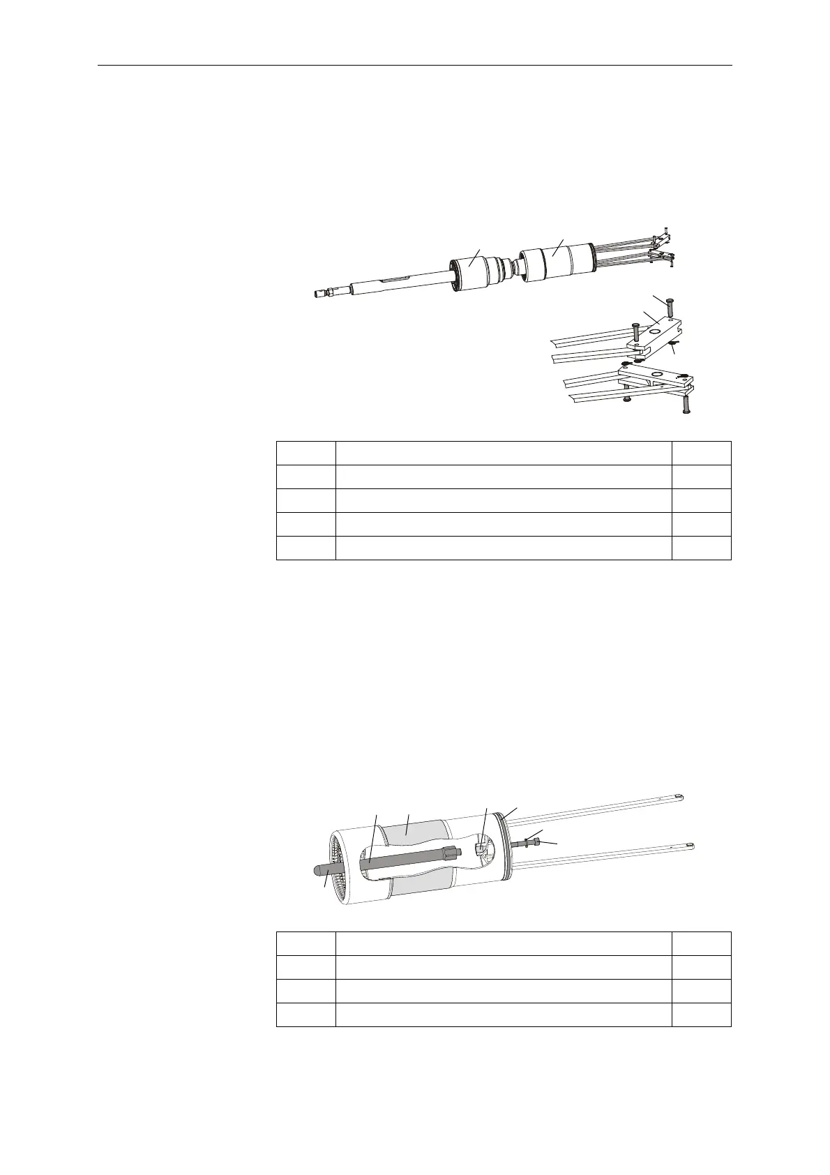
10.1.4 Disconnecting the Making and Breaking Units
• Remove the cotter pins (10) and flanged coupling pins (9) from
the two guide levers. We recommend tool T101 for removing the
cotter pins.
• Pull the interrupter unit out of the movable contact system.
10.1.5 Reconditioning the Movable Contact System
• Replace the arcing contact pin (29). Lubricate the contact
surfaces per lubrication specification L6. Tighten the screw (30) to
a torque of 17Nm.
• Replace the guide strip (11). The guide strip is located in a
dovetail groove. It is therefore necessary to overcome
mechanical resistance when replacing it.
• Lubricate the outer diameter of the movable contact system in the
area of the electrical sliding contact surface per lubrication
specification L6.
5 Interrupter unit 1x
6 Movable contact system 1x
8Guide lever 2x
9 Flanged coupling pin, 6x24 4x
10 Cotter pin, 8x1.2 4x
11 Guide strip 3x5x398 1x
15 Washer, 8 A2-70 1x
29 Arcing contact pin 1x
30 Socket head cap screw, M8x20 A-70 1x
 Loading...


