EasyManuals Logo
Home>GE>Circuit breakers>GL 313 F3/4031 P/VR

GE GL 313 F3/4031 P/VR User Manual

GE GL 313 F3/4031 P/VR
140 pages
To Next Page IconTo Next Page
To Previous Page IconTo Previous Page
Page #77 background imageLoading...
Page #77 background image
RECONDITIONING
REV6 /REV6 OI 248 (EN) 77
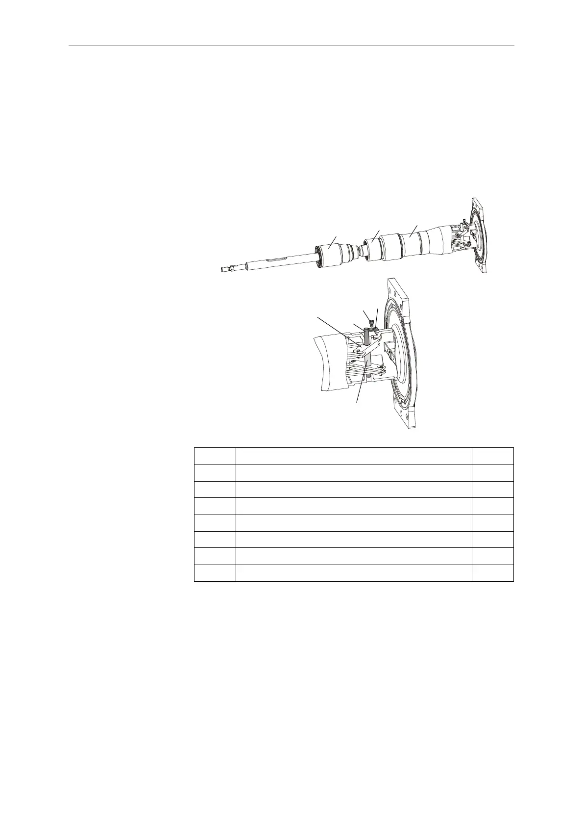
10.1.3 Removing the Guide Shaft
Remove the socket head cap screw (17) and the locking plate
(18).
Remove the guide shaft (28) and space sleeve (21) from the fixed
contact.
The interrupter unit is connected by the guide lever to the
movable contact system. Remove the interrupter unit, the guide
lever and the movable contact system from the fixed contact.
5 Interrupter unit 1x
6 Movable contact system 1x
7 Fixed contact 1x
8Guide lever 2x
17 Socket head cap screw, M8x12 A-70 1x
18 Locking plate 1x
21 Spacer sleeve 1x
28 Guide shaft 1x
5
7
6
17
8
28
18
21
BA-P-PS-3

Table of Contents

Questions and Answers:

Question and Answer IconNeed help?

Do you have a question about the GE GL 313 F3/4031 P/VR and is the answer not in the manual?

GE GL 313 F3/4031 P/VR Specifications

General IconGeneral
BrandGE
ModelGL 313 F3/4031 P/VR
CategoryCircuit breakers
LanguageEnglish

Related product manuals