RECONDITIONING
86 OI 248 (EN) REV6 /REV6
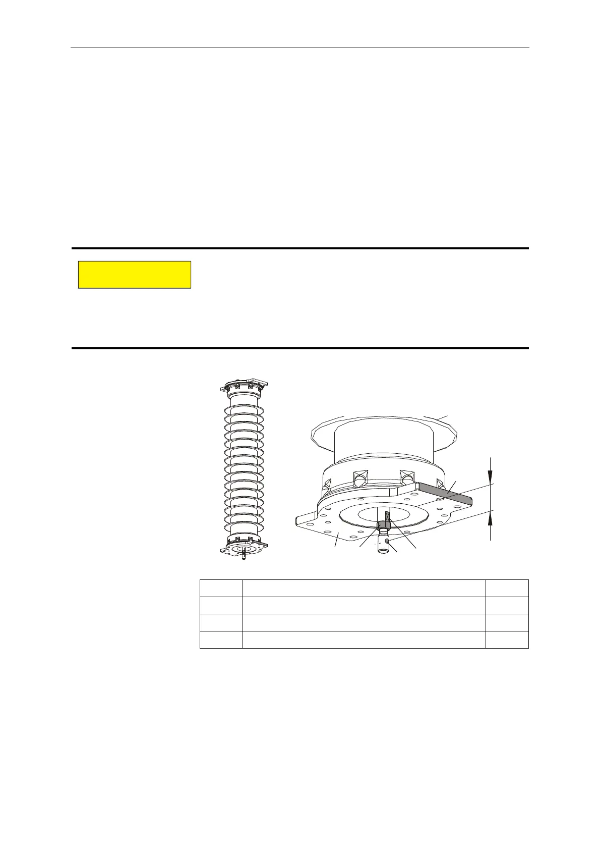
10.1.12 Adjusting the Double Motion System
• Pull the interrupter unit down until it touches the stop (required
tensile force approx. 200N).
• Align the flattened sides of the connecting rod (31) so that they
are parallel with the high voltage terminal pads (32). Alignment is
accomplished by turning the interrupter unit.
• Adjust the distance between the lower edge of the holder (16) and
the center of the hole in the coupling piece (33) to 69.5±1mm. The
hole in the coupling piece (33) and the flattened sides of the
connecting rod must be aligned in the direction of the high voltage
terminal pads.
• Tighten the nut (34). Tighten to a torque of 130Nm.
Improper adjustment of the interrupter unit can result in damage
during operation.
Therefore:
Carefully adjust and check the following:
- Distance of 69.5±1mm.
- Alignment of the flattened connecting rod side.
- Alignment of the hole in the coupling piece.
31 Connecting rod 1x
32 High voltage terminal pad 1x
33 Coupling piece 1x
34 Hexagon nut, M20x1.5 A2-70 1x
 Loading...


