RECONDITIONING
80 OI 248 (EN) REV6 /REV6
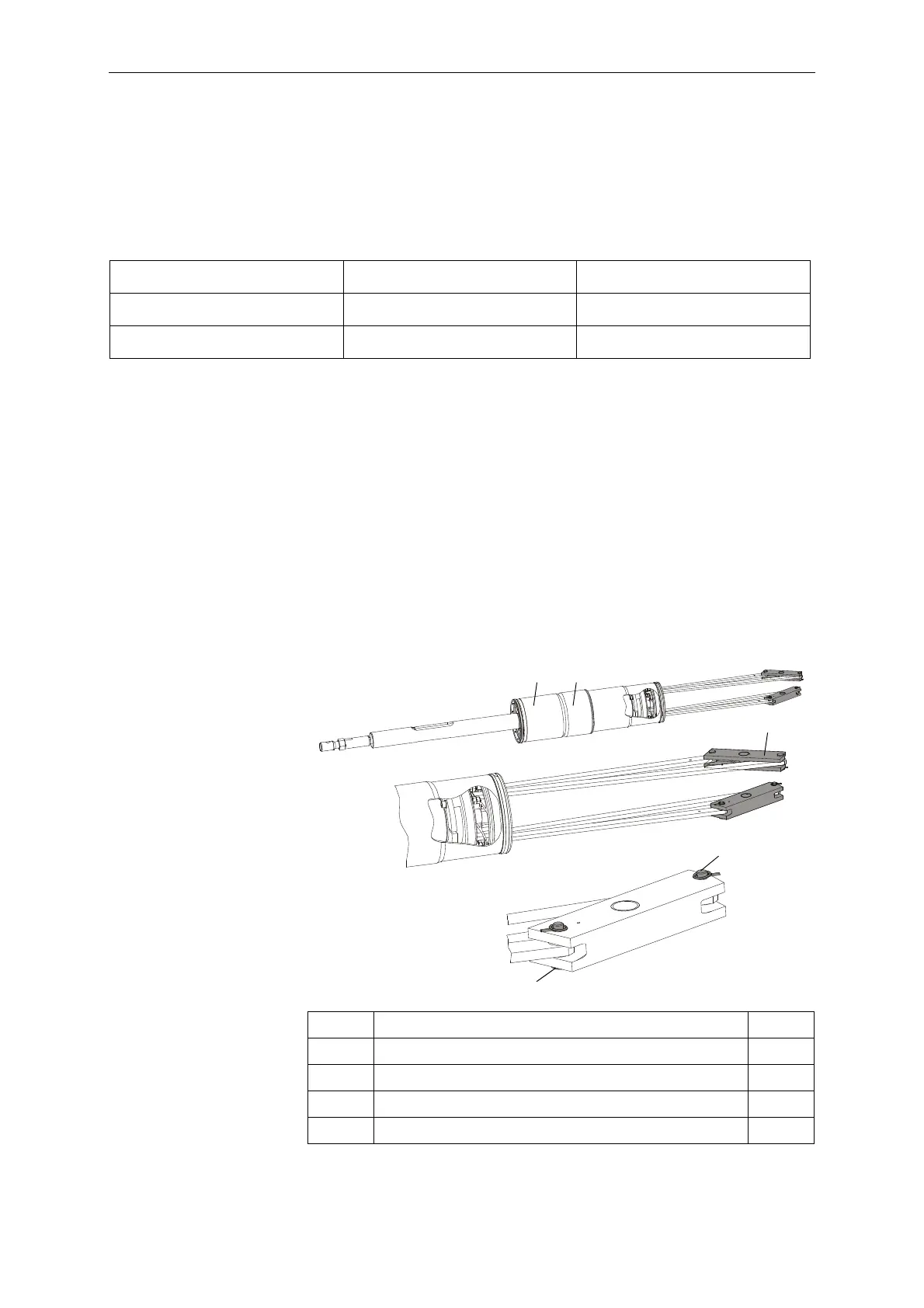
10.1.8 Connecting the Making and Breaking Units
The two lever arms of the guide lever are not identical. Matching
them up with the guide rods is facilitated by an identification sys-
tem.
Identification System
• Insert a new interrupter unit into the movable contact system until
it hits the stop. As you do so, insert the rods of the interrupter unit
through the large holes in the movable contact system.
• Lubricate new flanged coupling pins (9) per lubrication
specification L7.
• Insert the rods of the movable contact system into the guide
levers, selecting the lever arm marked with a dot.
• Insert the rods of the interrupter unit into the guide levers,
selecting the lever arm that is not marked with a dot.
• Insert a new flanged coupling pin (9) from the outside into the
rods and levers.
• Secure it with a new cotter pin (10). We recommend tool T101 for
installing the cotter pins.
Guide lever Guide rod
Movable contact system Dot mark Dot mark
Interrupter unit No dot mark No dot mark
5 Interrupter unit 1x
6 Movable contact system 1x
8Guide lever 2x
9 Flanged coupling pin, 6x24 4x
10 Cotter pin, 8x1.2 4x
 Loading...


