INSTALLATION
34 OI 248 (EN) REV6 /REV5
6.8 Installing the Pole Columns
The operations described in this section must be carried out in se-
quence for each of the three pole columns. The poles themselves
can be installed in any order desired.
6.8.1 Erecting the Pole Columns
• Check the serial number (S) and identifying pole letter on the
lower insulator flange or on the crankcase flange.
• Check to make sure the serial number agrees with the breaker
serial number.
• Place a wooden board (3) under the rounded area at the bottom
of the pole column. This will protect the pole column during the
erection process.
• Fasten the lifting tackle to the pole column using two M16
eyebolts. Use the two middle holes in the terminal pad mounting
plate for this purpose.
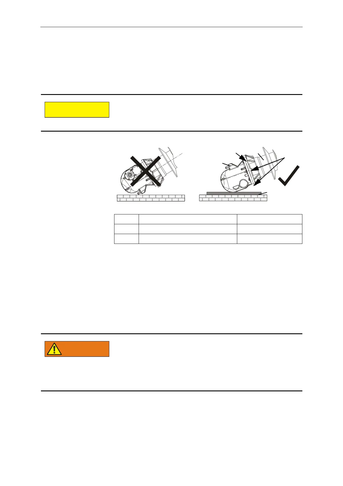
The filling connection (2) of the pole column (1) must face up-
ward during the erection procedure. If the filling connection faces
downward, it could be easily damaged during erection.
1 Pole column -
2 Filling connection -
3 Wooden board Not supplied
Falling loads can result in serious personal injury and damage to
the breaker.
Therefore:
- Never lift the pole columns from the high voltage terminal
pads attached to the pole column. Always use the holes in
the terminal pad mounting plate.
- Do not stand under suspended loads.
 Loading...


