INSTALLATION
26 OI 248 (EN) REV6 /REV5
6.4.2 a Unpacking Pole Column with Composite Insulators
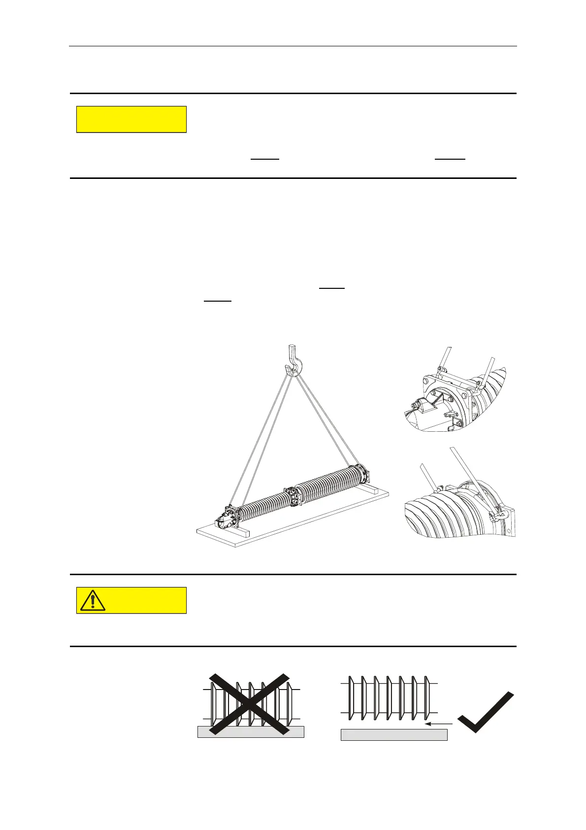
• Place two squared timbers on the ground as supports for the pole
column. The pole column must be deposited on the lowermost
and uppermost insulator flange, and the squared timbers must be
spaced accordingly. The insulator sheds must not come in
contact with the squared timbers or the ground, and the
dimensions of the squared timbers must be selected accordingly.
• Attach slings and appropriate lifting accessories (shackle, eyebolt
or lifting eye nut) to the lower
flange of the post insulator and the
upper
terminal pad mounting plate.
• Lift the pole column out of the packaging and lower it on to the
squared timbers.
Attaching lifting tackle to the silicone surface can damage the in-
sulator.
Therefore:
- Attach lifting tackle solely to the fastening points provided
(on the lower
post insulator flange and the upper terminal
pad mounting plate).
Contact with the ground may damage the insulators.
Therefore:
- Select squared timbers of sufficient height, and position
them correctly in order to prevent the insulators from tou-
ching the ground.
 Loading...


