TROUBLESHOOTING
REV6 /REV2 OI 248 (EN) 65
8.3.1 Austausch einer Gasverbindung
The standard gas connection consists of bent tubes. It is firmly
connected to the density monitor unit on one side. The other side
has a filling coupling with check valve for connection to the pole
columns.
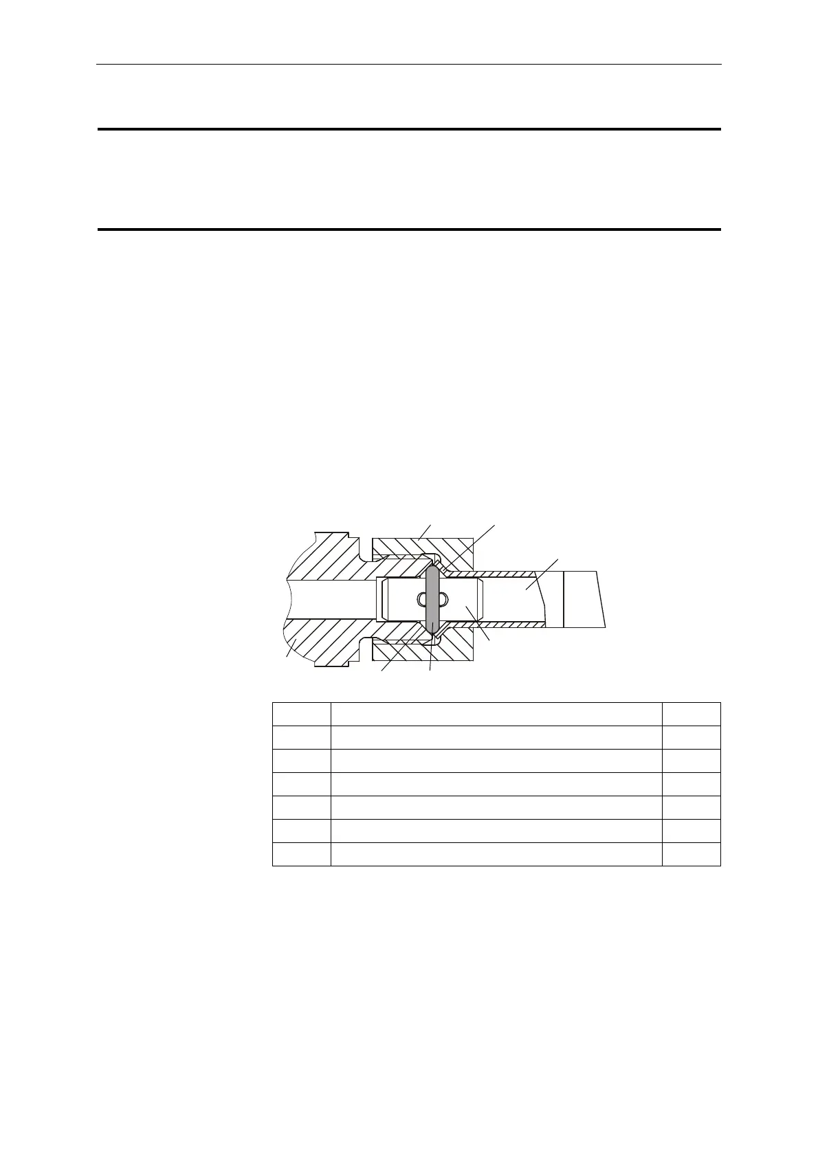
The ends of the gas pipes (1) are flared (1a). The inner surface of
the flaring is the sealing surface. The gas pipes are connected by
union nuts (1b). The flaring allows the union nuts to be captivated
to the gas pipe.
The piping junction points (2) have an external thread and an inside
tapered contour (2a). The inside tapered contour forms the sealing
surface.
A tubular stiffener (3) stabilizes the joint mechanically. The O-ring
(4) fitted onto the stiffener seals the connection.
• Disconnect all filling connections. This will disconnect the gas
compartments of the pole columns from the gas piping.
• Unscrew the gas pipe that is to be replaced from the junction
points.
• Check the sealing surfaces of the junction points for damage.
• Apply grease to a new O-ring (4) as per L5 and fit onto the tubular
stiffener (3).
• Lubricate the sealing areas on the gas pipe and the junction
points as per L5.
In one equipment version, the switchgear is available with a gas
connection of type FlexLink.
The FlexLink technology makes it particularly easy to couple the
gas connections to the pole columns. (see Chapter “12.2” on
page 101)
1 Gas pipe 1x
1a Flaring -
1b Union nut -
2 Junction point -
2a Inside tapered contour -
3 Tubular stiffener 1x
4 O-ring 1x
 Loading...


