GE PROPRIETARY TO GE
D
IRECTION 5308917-100, REVISION 8 LOGIQ P3 SERVICE MANUAL
8-18 Section 8-2 - Disassembly/Re-assembly of LOGIQ P3
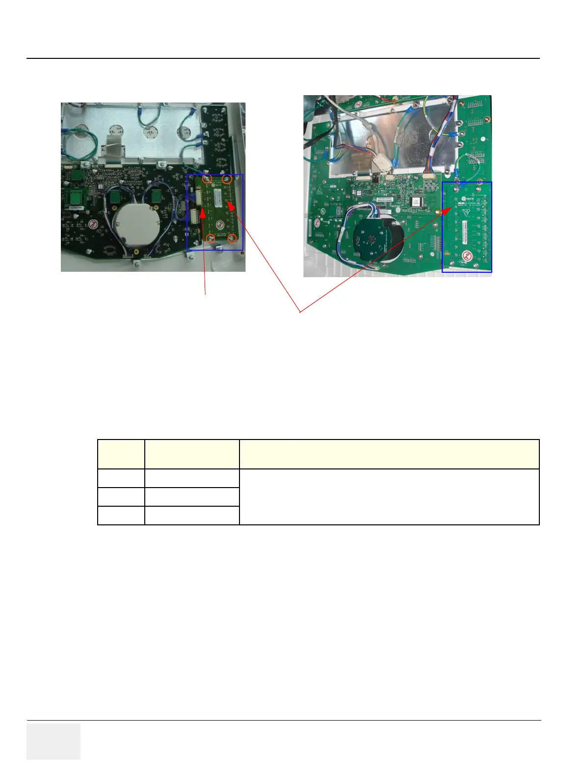
Figure 8-18 TGC PCB
8-2-9-6 Mounting procedure
1.) Install the new parts in the reverse order of removal.
8-2-9-7 Functional Checkout Procedure
See
Section
Functional Test Debrief Script
4-3-1 Power On/Boot Up
Service Manual Direction 5308917-100, Section 8-2-7. Equipment passes all required
tests and is ready for use.
4-3-2 Power Off/ Shutdown
4-3-6 B Mode Checks
TGC Interface cable
TGC Assembly
LOGIQ P3
LOGIQ P3 BT
 Loading...


