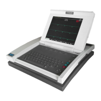
5-12 MAC 5500 resting ECG analysis system Revision E
2020299-020
Maintenance: Disassembly Guidelines
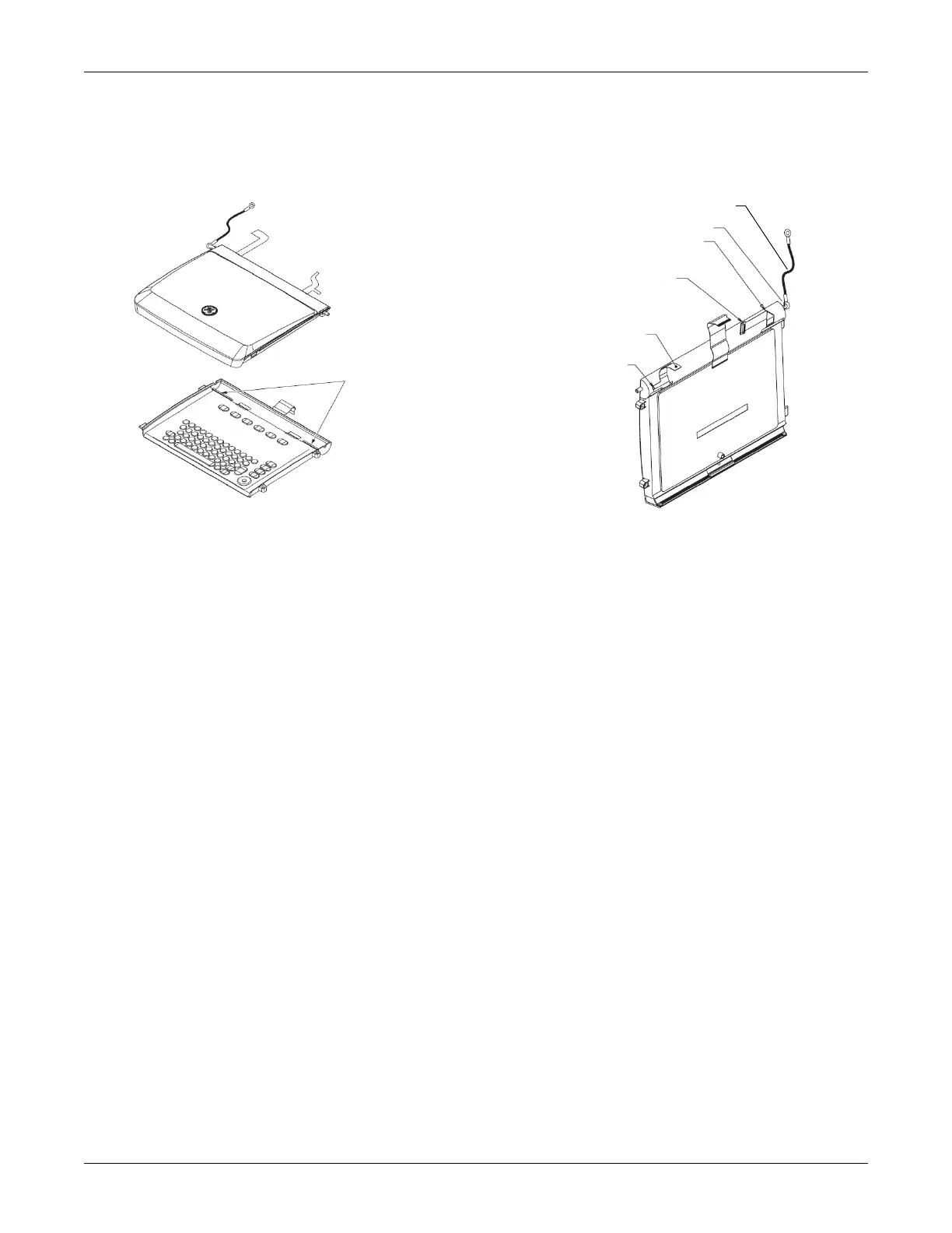
Display/Keyboard Reassembly
1. Insert both flex cables through flex cable slots and position them as shown.
2. Tilt the display/keyboard assembly to the left and with the roll pin of the hinge
(metal rod)
parallel to the left hinge base, insert the rod into the left hinge base
and lower the display/keyboard assembly in place.
3. Slide tabs into their mounting slots and set the display/keyboard assembly in
place.
4.
Connect the three cables from the display/keyboard
assembly to the main PCB.
Be sure to lift the locks up prior to attempting to insert the cables into the
connectors.
5. Slide the display hinge (metal rod) to the right until it locks into the right hinge
base.
6. Replace the hinge bracket with the two TO
RX screws removed earlier.
7. Replace the screw and display ground at the left of the hinge rod.
8. Replace the two TORX mounting screws on the right side of assembly.
Reassembly
1. Raise the display to the vertical position.
2. Make sure the bezel surrounding the rear panel
connectors is in place. Make
sure the release mechanism for the Smartmedia card functions properly.
3. Lower the top cover down around the display and set in position.
4. Snap the rear of the top cover in place and then, gently pulling on the
thin
pla
stic strip at the front of the top cover, position it in place under the keyboard
assembly.
5. Replace the screws removed in disassembly.
45A
44A
Align Flex to Pin
Flex Cable
Slots
Display Ground
LCD Flex Cable
Backlight
Flex Cable
Backlight Flex Cable
LCD Flex Cable
Fasten to writer as shown
Roll Pin
Display Ground
 Loading...