2-14 MAC 5500 resting ECG analysis system Revision E
2020299-020
Equipment Overview: Theory of Operation
Boot Loader
In the -005 board, after power ON, the FPGA gets configured using the micro
controller Curly. The FPGA emulate the boot ROM and the start up code was placed
in the Boot ROM from the smart media card by the micro controller Curly.
The ATMEL AT91RM9200 has built in boot program in the internal ROM. The
-006 and -007 boards utilize the ATMEL CPU itself for bringing up the board. Since
the service of Curly is no longer required, it is removed from the board. At power
ON if the BMS pin is high, ATMEL starts executing boot code in the internal ROM.
The boot program looks for valid code in SPI data flash (U66) and, if found,
downloads the program into SRAM and starts executing from SRAM after remap.
The -006 and -007 boot program loads primary boot code into the SDRAM after
initializing it. The primary boot program reads the PCB ID code from three port pins
and then searches the NAND Flash for a matching FPGA configuration image
(pages with ID “Xn” where n is the 3-bit PCB ID code 1-8 plus one). Once located,
the configuration image is loaded into the FPGA in fly-by fashion. Blinking of LED
DS3 at 1 Hz indicates successful completion of FPGA configuration. The primary
boot program then loads the secondary boot code from NAND to SDRAM and
transfers the control to the secondary boot program. Buffer U55 is used to get the
direct CPU access to NAND Flash. To configure the FPGA in fly-by mode, the data
needs to be present at the Xbus while toggling CCLK. This is achieved by toggling
the NAND_RE* alternately with CCLK. The NAND_RE* needs to be under the
GPIO control instead of static memory controller to do this. The ALE and CLE are
also controlled in GPIO mode and tied to low level during read cycle while
configuring the FPGA. The CLE and ALE acts as address line A23 and A25
respectively during Address and command cycle as well as access other than FPGA
configuration. The reason for omitting A24 is because of AT91RM9200 silicon bug.
The A24 does not work like an address pin. It can work only as GPIO line.
The primary boot code also contains the application for software update. If there is
no valid code in the NAND FLASH, the primary boot code looks for SD Card and if
detected it down load the code from the SD Card to NAND Flash and reset the
system. If the primary boot code can not detect a valid code within 2 minutes 6
seconds, Moe shuts down the system. The status of software update is indicated on
DS1 and DS2. The DS1 and DS2 are not visible once the top cover is in place. The
Moe flashes amber charge LED at 1Hz to indicate that software update is in
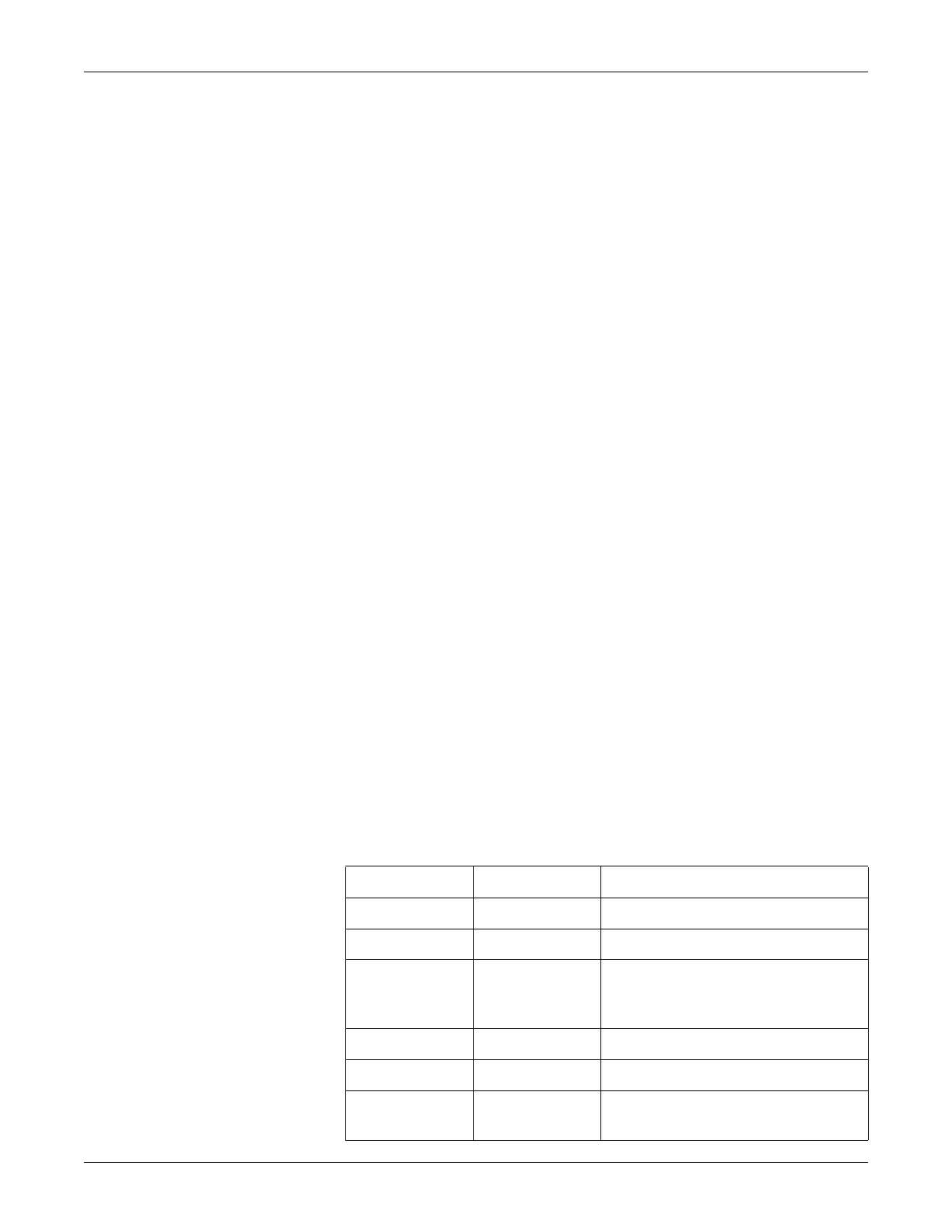
progress. But it can not provide the completion status. Refer the table below for the
status messages from LEDs DS1 and DS2 during primary boot software update.
DS1 Red DS2 (Green) Status
Off Flashing No SD card detected for software updated
Off‘ On Copying image files from SD card to SDRAM
Off Off Erasing and / or formatting the NAND Flash.
Applicable only during the software update
process.
On Off Programming the NAND Flash
Flashing Flashing Successful completion of programming
Flashing Off Error - Could program all the image files. But
error in programming the status page 'Z0'.