Revision E MAC 5500 resting ECG analysis system 5-19
2020299-020
Maintenance: Disassembly Guidelines
Printhead Replacement
Removal
1. Remove the top cover following the procedure above.
2. Using a Phillips head screw driver, remove the two screws that hold the
printh
ead to the printhead mounting plate.
3. Open the writer assembly, disconnect
and remove the printhead.
Reassembly
1. Record the resistance value of the new printhead.
2. Connect the new printhead to the ribbon cable.
3. Hold the new printhead FIRMLY in place against the two metal
tabs on the
printhead mounting plate, then tighten the two screws.
4. Replace the top cover and power up the unit.
5. Go to the Setup menu and enter the new printhead resistance value.
6. Run a Writer Test test (See Chapter 5).
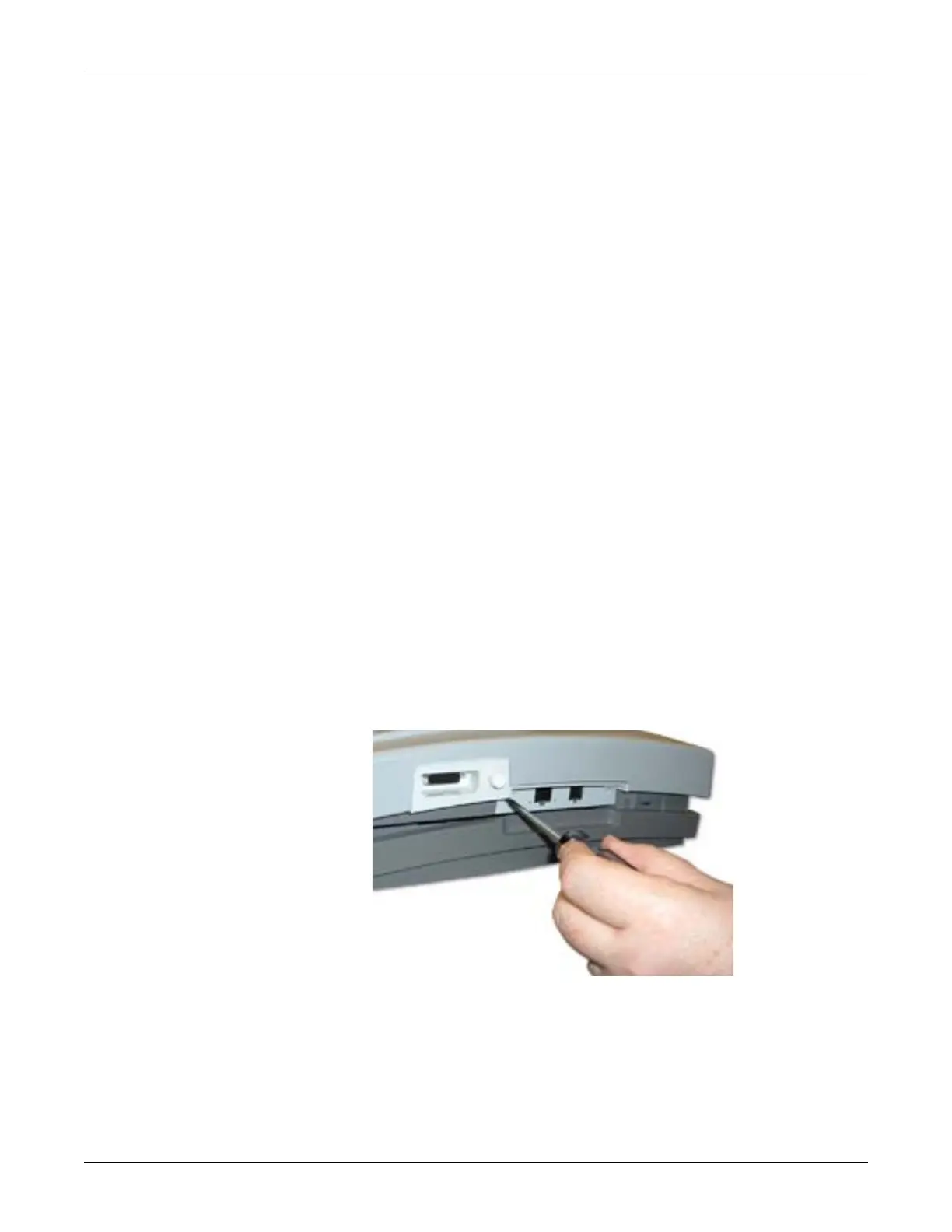
COMM Board Replacement
Use the following procedure to replace the communications board.
1. Remove the AC power cable and battery.
2. Using a Torx #10 screwdriver, remove the two screws from the panel
surroundin
g the LAN and modem ports.
3. Grasp the side edges of the communications board and work it back and forth in
th
e slot as you pull it out along its rails.
 Loading...