8-148 Section 8-6 - Mechanical Parts- Replacement Procedures
D
IRECTION 5771498-100, REVISION 6 VENUE™ SERVICE MANUAL
PRELIMINARY
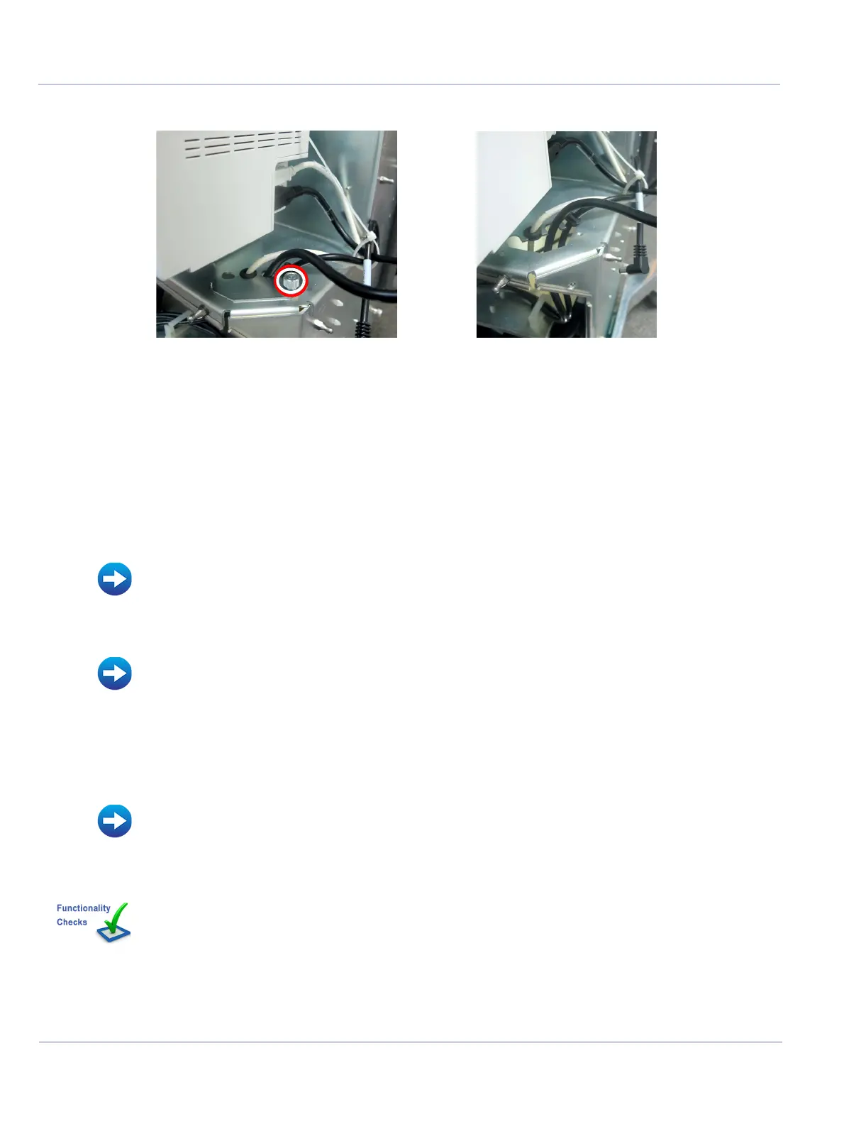
4.) Loosen the Phillips screw and remove the Peripheral Cable Cover.
5.) Disconnect the printer cable (yellow USB connector) from the Back End assembly.
8-7-9-5 Printer USB Cable Installation Procedure
1.) Connect the new printer cable to the Back End assembly.
2.) Route the printer cable through the dedicated cable opening in the eTower.
3.) Attach the Peripheral Cable Cover and secure with Phillips captive screw.
NOTE: Make sure the Peripheral Cable Cover is properly aligned and affixed.
4) Install MPB Front Metal Door.
5.) Refit the following covers: RS Probe Cover, Lower Front eTower, Left side eTower, Right Side
eTower, Upper eTower Front Cover.
6.) Install all accessories.
7.) Turn ON power to the system.
Figure 8-150 Disconnecting the Printer Cable
• MPB Front Metal Door Installation Procedure
• Upper eTower Front Cover Installation Procedure
• Left Side eTower Cover Installation Procedure
• Right Side eTower Cover Installation Procedure
• Lower Front eTower Cover Installation Procedure
• RS Probe Cover Installation Procedure
• Accessories - Replacement Procedures
Perform the checks listed in Printer USB Cable Replacement Procedure on page 8-218

 Loading...


