ADV200 • Quick start up guide 189
If the safety function is not required, the safety enable command (SFTy ENABLE) must still be sent to
PIN1 terminal TB1 on the INT-P-ADV card to enable the drive.
For instructions on connecting and commissioning the safety card with the SIL2 or SIL3 safety level
function, please see chapter 7 “Application Examples” in the STO Safety Interface manual (code
1S5F94) in the CD supplied with the drive or which you can download from www.gefran.com.
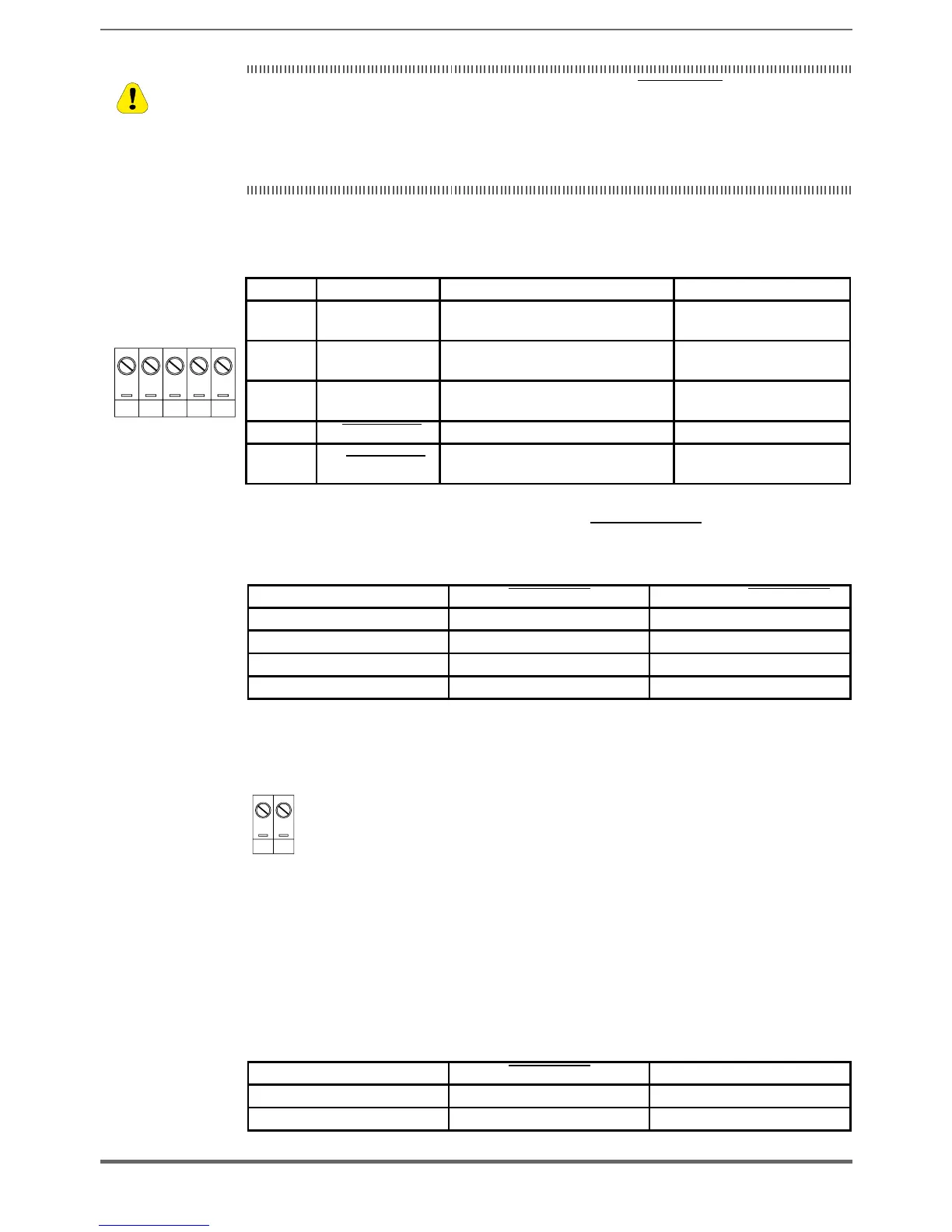
TB1 terminal
Terminal Signal name Function Description Electrical limits and range
543
5 O-
+0 COM power supply for alarm
feedback circuit
(IN) 0V
4 FB
+24V@100mA output feedback signal
SAFETY DISABLED
(OUT) 0…35V; 150mA
maximum DC current
3 O+
+24V power supply for alarm feedback
circuit
(IN) +5v…35v with respect
to #5
2
- (SFTy ENABLE) 0V COM for disabling the safety function (IN) 0V
1
+ (SFTy ENABLE) +24v for disabling the safety function
(IN) +12…+35v with
respect to #2
State of feedback to terminal TB1-4 based on (SFTy ENABLE) command to pins
1, 2 and of ENABLE control to pin 7 of the R-ADV200 card:
CONTROLLER ENABLE (SFTY ENABLE) FB Feedback (SFTY ENABLE)
24V OPEN O-
OPEN 24V O+
OPEN OPEN O-
24V 24V O+
TB2 terminal
SAFETY STATUS digital output ad OPTOMOS: 0…35V, 150mA max
Terminal TB2 provides a digital output to OPTOMOS (SAFETY STATUS), which
is not used in the safety chain but can be used to signal the STO state to the R-
ADV200 control card (via digital input).
A typical application can be to program as DRIVE INTERLOCK the source of the
digital input to which +24V is delivered via the SAFETY STATUS output.
When the STO function is disabled (24V present between terminals 1 and 2 of
TB1), the contact (SAFETY STATUS) between pins 1 and 2 of TB2 is closed
CONTROLLER ENABLE (SFTY ENABLE) FB2 Feedback (SAFETY ENABLE)
24V OPEN Open
OPEN 24V Close
Caution

 Loading...


