Ch.561
—————— Wiring procedure ——————
5. WIRING PROCEDURE
5.1. ACCESSING TO THE CONNECTORS
5.1.1 Removing the Covers
NOTE! Observe the safety instructions and warnings given in this manual. The devices can be
opened without the use of force. Only use the tools specified.
See figure 3.2.2 “Drive view & components” to identify the single part.
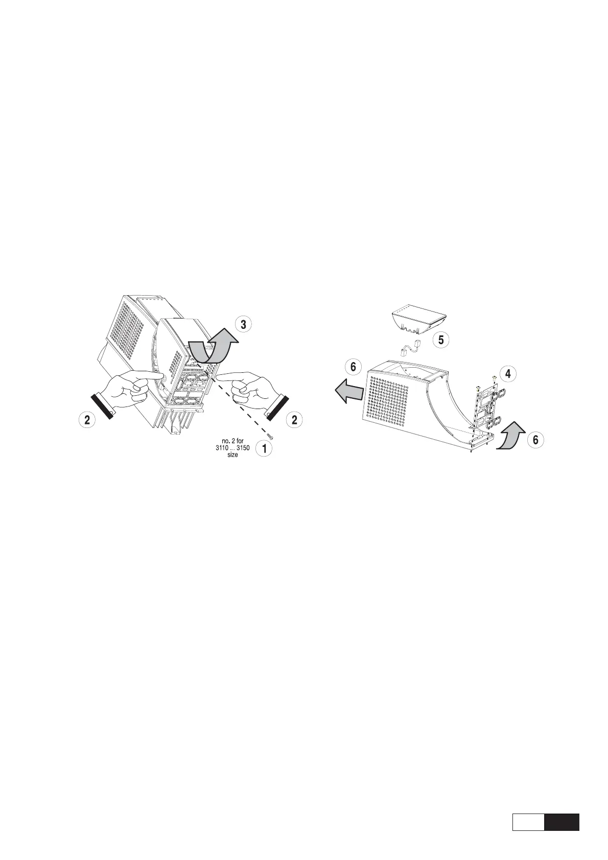
Figure 5.1.1: Removing the covers (sizes 1007 to 3150)
Sizes 1007 to 2075
The terminal cover and cable entry plate of the device must be removed in order to fit the electrical connec-
tions:
- unscrew the screw (1), remove the cover of devices (2) by pressing on both sides as shown on the above
figure (3).
- unscrew the two screws (4) to remove the cable entry plate.
The top cover must be removed in order to mount the option card and change the internal jumper settings:
- remove the keypad and disconnect the connector (5)
- lift the top cover on the bottom side (over the connector level) and then push it to the top (6).
Sizes 3110 to 3150
The terminal cover and cable entry plate of the device must be removed in order to fit the electrical connec-
tions:
- unscrew the two screws (1) and remove the cover of devices
- unscrew the two screws (4) to remove the cable entry plate.
The top cover must be removed in order to mount the option card and change the internal jumper settings:
- remove the keypad and disconnect the connector (5)
- lift the top cover on the bottom side (over the connector level) and then push it to the top (6).

 Loading...


