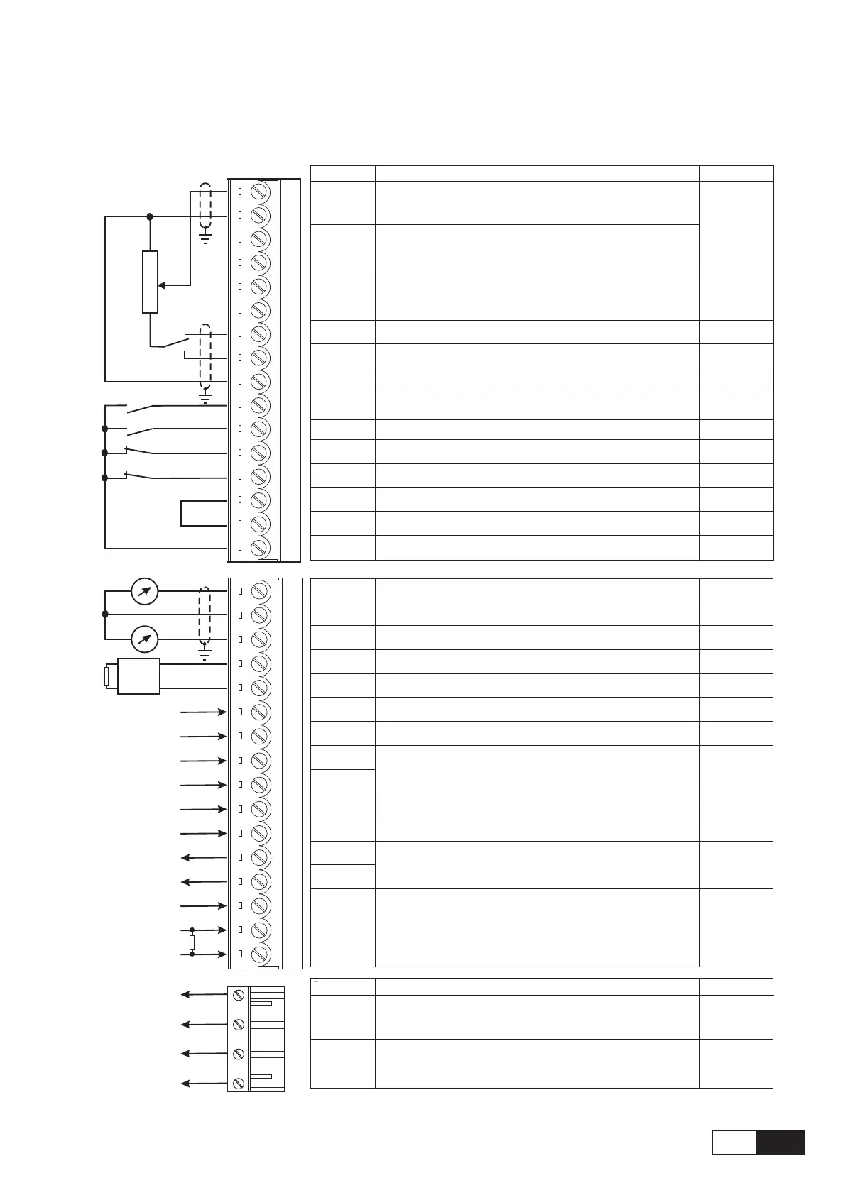
5.3.2. Terminal Assignments on regulation section
1
2
3
4
5
6
7
8
9
12
13
14
15
16
18
19
BU-
External braking
unit (optional)
Strip X1
Function
max
Programmable/configurable analog differential input. Signal: terminal 1.
Reference point: terminal 2. Default setting: Ramp ref 1
±10V
Programmable/configurable analog differential input. Signal: terminal 3. 0.25mA
Reference point: terminal 4. Default setting: none (20mA when
Programmable/configurable analog differential input. Signal: terminal 5.
current ref
input)
Reference point: terminal 6. Default setting: none. (1)
+10V
Reference voltage +10V; Reference point: terminal 9 +10V/10mA
-10V
Reference voltage -10V; Reference point: terminal 9 -10V/10mA
0V
Internal 0V and reference point for±10V -
Enable drive
Inverter enable; 0V or open: inverter disabled; +15…+30V: Inverte enabled
+30V
Start
Inverter start command; 0V or open: No start; +15…+30V: Start 3.2mA @ 15V
Fast stop
OV or open: Fast stop. +15…+30V: No Fast stop.
5mA @ 24V
External fault
OV or open: External fault. +15…+30V: No External fault
6.4mA @ 30V
COM D I/O
Reference point for digital inputs and outputs, term.12...15, 36...39, 41...42
-
0V24
Reference point for + 24V OUT supply, terminal 19 -
+24V OUT
+24V supply output. Reference point: terminal 18 or 27 or 28
+22…28V
120mA @ 24V
Analog input 1
Analog input 2
Analog input 3
Analog output
1
Program.analog output; def.setting: Motor speed. Ref. point: term.22
±10V/5mA
0V
Internal 0V and reference point for terminals 21 and 23
-
Analog output
2
Program.analog output; def.setting: Motor current. Ref. point: term.22
±10V/5mA
BU comm.
output
VeCon controlled BU-... braking units command. Ref. point: term.27.
+28V/15mA
0V24
Reference point for BU-... command, terminal 26
-
RESERVED -
Digital input 1 +30V
Digital input 2 3.2mA @ 15V
Digital input 3 5mA @ 24V
Digital input 4 6.4mA @ 30V
Digital output
1
+30V/40mA
Digital output
2
Supply D O
Supply input for digital outputs on terminals 41/42. Ref. point: term.16.
+30V/80mA
Motor PTC
1.5mA
Programmable digital output; default setting: none
Motor PTC sensing for overtemperature (cutoff R1k if used)
Programmable digital input; default setting: none
21
22
23
26
27
28
29
36
37
38
39
41
42
46
78
79
R1K
Strip X2
Function max curr.
250V AC
1 A AC11
250V AC
1 A AC11
OK relay
contact
Potential-relay contact configurable (relay 2).
Default: open 0 drive stopped
Relay 2
contact
Potential- relay contact OK relay (closed=OK)
80
82
83
85
RESERVED
Programmable digital input; default setting: none. Configurable as 1st encoder
index qualifier (”Digital input 4” parameter must be set 0=OFF ).
Progr. digital input; def. setting: none. Configurable as 2nd encoder index qualifier
(setting via S30 jumper, )”Digital input 3” parameter must be set 0=OFF

 Loading...


