AVy - HGB
Ch.5 90
Full load losses Plfl are:
fA029
P
lfl
P
m
1-h
m
h
m
=
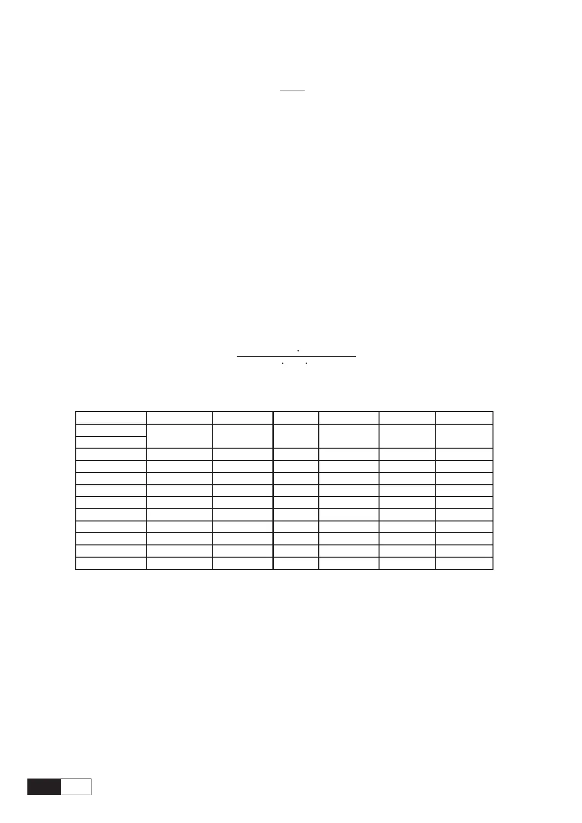
Maximum power supply drop out time (Buffer time/voltage failure buffer) of AVy is achieved by adding the
maximum recommended capacitance to the DC bus.
The following table show the maximum power supply drop out time for different Undervoltage thresholds
and inverter sizes. The meaning of the symbols in the colums is as follows:
C
std
= internal capacitance (in uF),
C
ext
max
= max external total capacitance (in uF),
T
buff
= max drop out time (in sec.),
P
SMPS
= power supply (watts),
U
buff
= volts threshold to disable drive operation (in volt),
U
min
= min DC volts that will support the power supply (in volt)
Where T
buff
is defined by:
T
buff
(CCmax) (U - U)
std + ext buff min
22
2P 10
SMPS
6
=
Table 5.10.1: Drive Trip Times, 230-V Threshold
Size P
SMPS
C
std
C
ext
max U
buff
U
min
T
buff
4185
4220
4300 70
2200
4500 230 200
0.62
4370 70
3300
4500 230 200
0.72
5450 70 4950 4500 230 200
0.87
5550 70 4950 4500 230 200 0.87
6750 70 6600 0 230 200 0.61
7900 70 6600 0 230 200
0.61
71100 70
9900
0 230 200
0.91
71320 70 14100 0 230 200 1.3
81600 70 14100 0 230 200 1.3
82000 70 14100 0 230 200 1.3
avy4225
200 0.5870 1800 4500 230

 Loading...


