AVy - HGB
Ch.5 86
5.8.3. Calculation of generic external braking resistor to be combined with the
internal braking unit with an approximate method
In order to calculate resistor values different from the one stated in the table 5.8.2.1 (having, for example,
different values of turn-on threshold of the braking unit), the following remarks are valid:
the peak power dissipated by the resistor is P
PBR
= V
BR
2
/ R
BR
[W] , where “V
BR
” is the turn on voltage of the
braking unit (see table 5.8.2.2 ).
The requested maximum power P
MB
by the cycle must not be higher than this value: P
MB
≤ P
PBR
.
The braking resistor is normally used with an intermittent cycle. Therefore it is possible to use a resistor
capable of a continuous dissipated power lower than P
MB
.
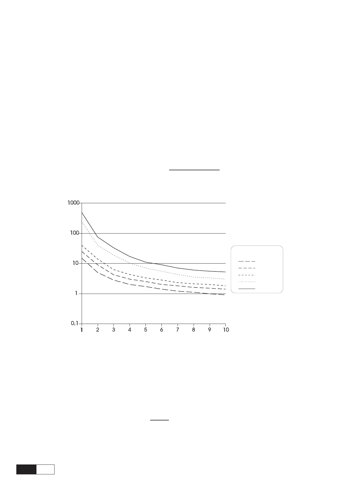
The following diagram is valid for rectangular load profile, it can be used in order to determine the overload
value. For triangular load profile, this diagram gives a safety conservative dimensioning (similar diagrams
can be provided by the manufacturer of the resistor to be used).
In order to calculate the value of the continuous power (or rated power) of the braking resistor , the overload
factor should be determined using the diagram, then the following formula must be applied:
Nominal Power P
MBR
=
fA003
Overload factor
P
MB
RESISTOR POWER
TIME OF OVERLOAD (sec. - log. scale)
OVERLOAD FACTOR
Pause Time
15 sec.
30 sec.
1 min.
5 min.
30 min.
Figure 5.8.3.1: Power Resistor Overload Factor
Example: In order to stop a 18.5 kW motor (38A at 400V) with a 150% overload, the max.
regenerated power is 27.75 kW. Assuming a 5-second braking time (overload time
for resistance) and 1-minute pause, the diagram gives a 3.9 overload factor.
Therefore, the resistor rated power will be:
PNBR
=
fA004
27750
3.9
@ 7100 W
As for types bigger than 5550 or for particular braking cycles, it is recommended to use one or more BU-32
external braking units.

 Loading...


