AVy - HGB
Ch.5 66
5.2.2. Terminal Assignment on Power section / Cable Cross-Section
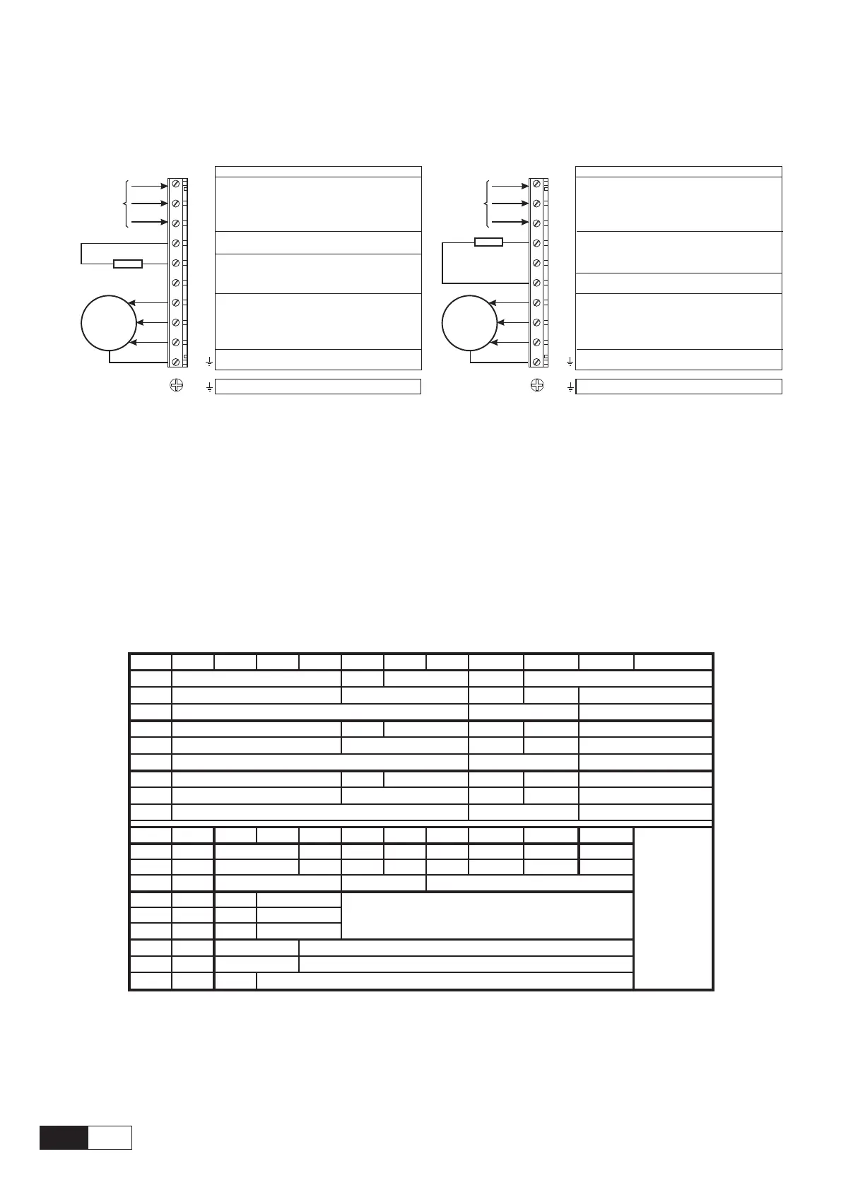
Figure 5.2.2.1: Power Terminals connection
Function (max) - Sizes 1007 … 3150
Motor ground connection
Braking unit resistor circuit (braking resistor
must be connected between BR1 and C)
DC link circuit connection
(770 V / 1.65 output current)
DC
AC mains voltage
(3x480 V +10% 3Ph,
AC
see table 3.3.2.1)
Motor connection
(AC line volt 3Ph, 1.36 output current)
Braking resistor
(optional)
M
3Ph~
PE1 /
Grounding (protective earth) conductor
U1/L1
V1/L2
W1/L3
BR1
U2/T1
V2/T2
W2/T3
C
D
PE2/
Motor ground connection
Braking unit resistor circuit (braking resistor
must be connected between BR1 and C)
AC mains voltage
(max 3x480 V +10%, see table 3.3.2.1)
AC
Braking resistor
(optional)
PE1 /
Grounding (protective earth) conductor
U1/L1
V1/L2
W1/L3
BR1
U2/T1
V2/T2
W2/T3
C
D
PE2/
M
3Ph~
Motor connection
(AC line volt 3Ph, 1.36 output current)
DC link circuit connection
(770 V / 1.65 output current)
DC
Function (max)- Sizes 4220… 81600
Power terminals lay-out
Sizes 1007 to 3150 The terminals of the devices are made accessible by removing the cover and the cable
entry plate (see section 5.1, “Accessing to the connectors”), on some drive type it is
also possible to extract the removable connector .All the power terminals are located
on the power card PV33-....shown on previous chapter.
Sizes 4220 to 81600: The terminals of the devices are made accessible by removing the cover (see section
5.1, “Accessing to the connectors”).
Maximum Cable Sizes for power terminals U1, V1, W1, U2, V2, W2, C, D, PE
Table 5.2.2.1: Maximum cable cross section for power terminals
1007 1015 1022 1030 2040 2055 2075 3110 3150 4185 4220
AWG
12 8
[mm2]
810
[Nm]
AWG
12 8 6
[mm2]
810
[Nm]
AWG
12 8 6
[mm2]
810
[Nm]
4300 4370 5450 5550 6750 7900 71100 71320 81600 82000
AWG
4 1/0 2/0 4/0 300* 350* 4xAWG2 * = kcmils
[mm2]
25 50 70 95 150 185 4x35 150** **: copper bar
[Nm]
3
AWG
88
[mm2]
10 10
[Nm]
1.6 1.6
AWG
6
[mm2]
16
[Nm]
33
avy4040
2
2
50
4
6
0.9
6
16
6
16
2
10
2
0.5 to 0.6 1.2 to 1.5
10
4
14
2
10
0.5 to 0.6
1.2 to 1.50.5 to 0.6
4
1.2 to 1.5
14 10
24
14
3
6
16
2
35
4 12 10-30
6
terminals not available
16
CAUTION! The grounding conductor of the motor cable may conduct up to twice the value of the rated
current if there is a ground fault at the output of the AVy Drive.
NOTE: Use 75°C copper conductor only.

 Loading...


