AVy - HGB
Ch.5 76
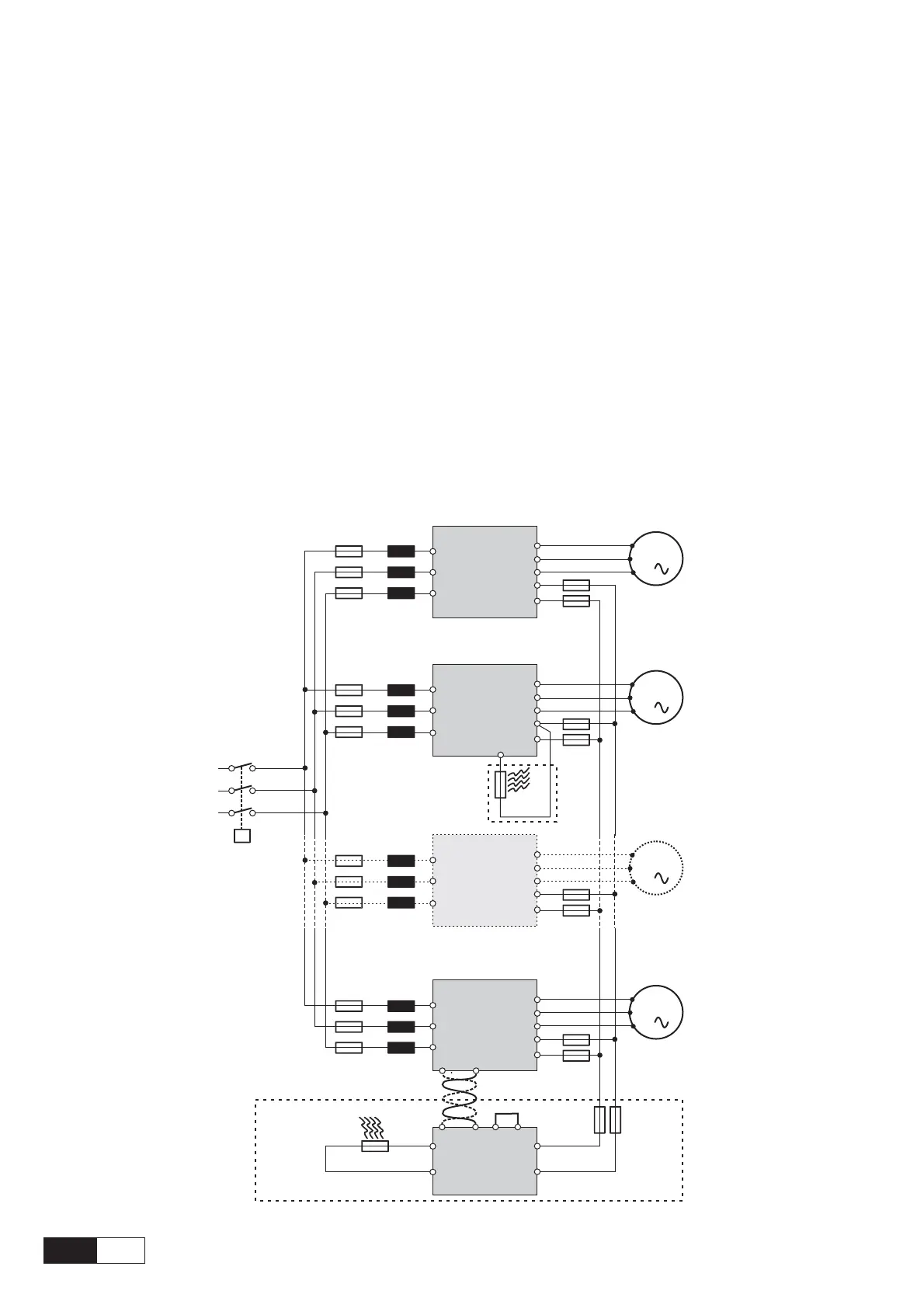
5.5.2. Parallel Connection on the AC (Input) and DC (Intermediate Circuit) Side of
Several Inverters
Features and Limits:
1 The inverters used have to be all the same size.
2 AC line chokes (see chapter 5.7.1) have to be the same (provided by the same supplier).
3 The mains power supply has to be simultaneous for all inverters, i.e. a single switch /line contactor has to
be used.
4 Such connection is suitable for a maximum of 6 inverters.
5 If necessary dissipate braking energy; a single internal braking unit (with external resistor) has to be used
or one (or several) external braking unit ("BU32-.., BUy-...”) configured with the inverter or a BU as
master (all the other connected BUs are configured as slaves).
6 Fast fuses (F12...F62) have to be fitted on the dc-link side ( C and D terminals) of each inverters (see
chapter 5.6.2).
(*) A
TTENTION ! Do not connect if external braking unit are used.
Figure 5.5.2.1: Parallel Connection on the AC and DC Side of Several Inverters
M1
3
M2
3
M6
3
F11 L1
F21 L2
F61 L6
U
V
W
U2
V2
W2
C
D
INVERTER 1
U
V
W
U2
V2
W2
C
D
INVERTER 2
BR
F12
F22
F62
U
V
W
U2
V2
W2
C
D
INVERTER 6
2627(0V24)
BR
CR
C
D
BU-32-...
(B y-...)U
(SLAVE)
78 910
R
BR
F7
R
BR
L1
L2
L3
K1
M..
3
F.. L..
U
V
W
U2
V2
W2
C
D
INVERTER ..
F..
(*)

 Loading...


