Ch.575
—————— Wiring procedure ——————
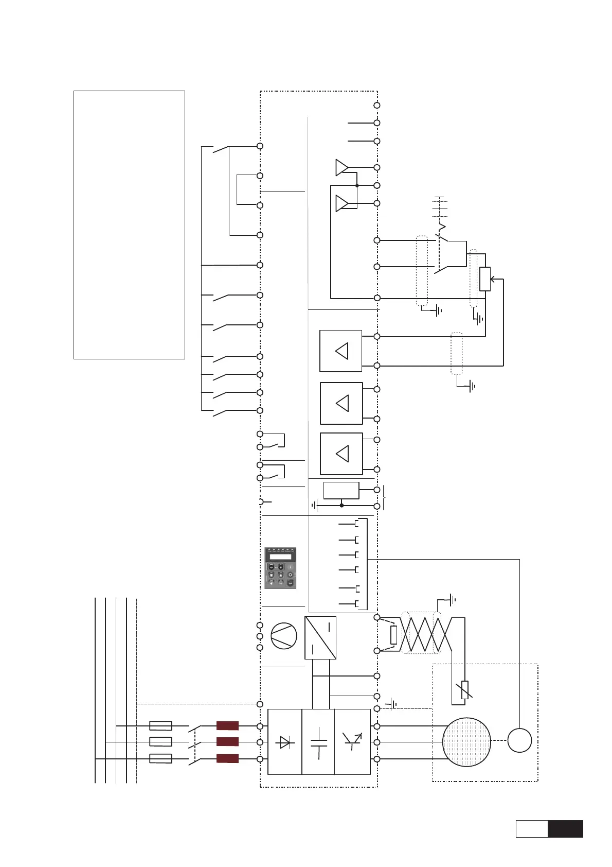
Figure 5.5.1.2: Typical connection
+ 24V
U1/L1
M1
K1M
5
F1
L1
L2
L3
N
PE
K2
G1
0 V24
C
D
1
2
3
4
6
K1M
SMPS
K0
L1
Thermistor
78
79
B-
1
A+
5
A-
6
B+
8
7
0V
9
5V
XE1
COM ID
19
18
16
15
External
Fault
14
13
12
Fast stop
Start
Enable
drive
80
82
83
85
ok
n>0
( default )
RS 485
Keypad
7
8
9
+10V
-10V
0V10
0
FWD
REV
R1
(2 ... 5 kOhm)
2
1
Analog input 1
Analog input 2
-
3
4
-
+
+
Analog input 3
5
6
-
+
E
*) R 1Kohm if
no thermistor
connected
*)
PE1
V1/L2
W1/L3
U2/T1
V2/T2
W2/T3
Dig. Inp.1
Dig. Inp.2
Dig. Inp.3
Dig. Inp.4
Analog
output 2
Analog
output 1
21
22
23
42
46
41
+30V
Dig. Out.1
Dig. Out.2
27
26
BU
1V3
U3
2V3
Optional from 22kW
up to 55kW
M
3~
The circuit diagram is for the
standard configuration of the
drive as delivered.
EMC installation and wiring
techniques are not shown.
For this see appropriate
chapter.
The connection of option
card is also shown
separately.
The automatic restart of the
drive after a failure alarm is
not included.
L1 : Insertion of an AC mains
inductance the power supply
input of the power supply
unit is compulsory (for the
type of inductance, consult
the manual of the power
supply unit).

 Loading...


