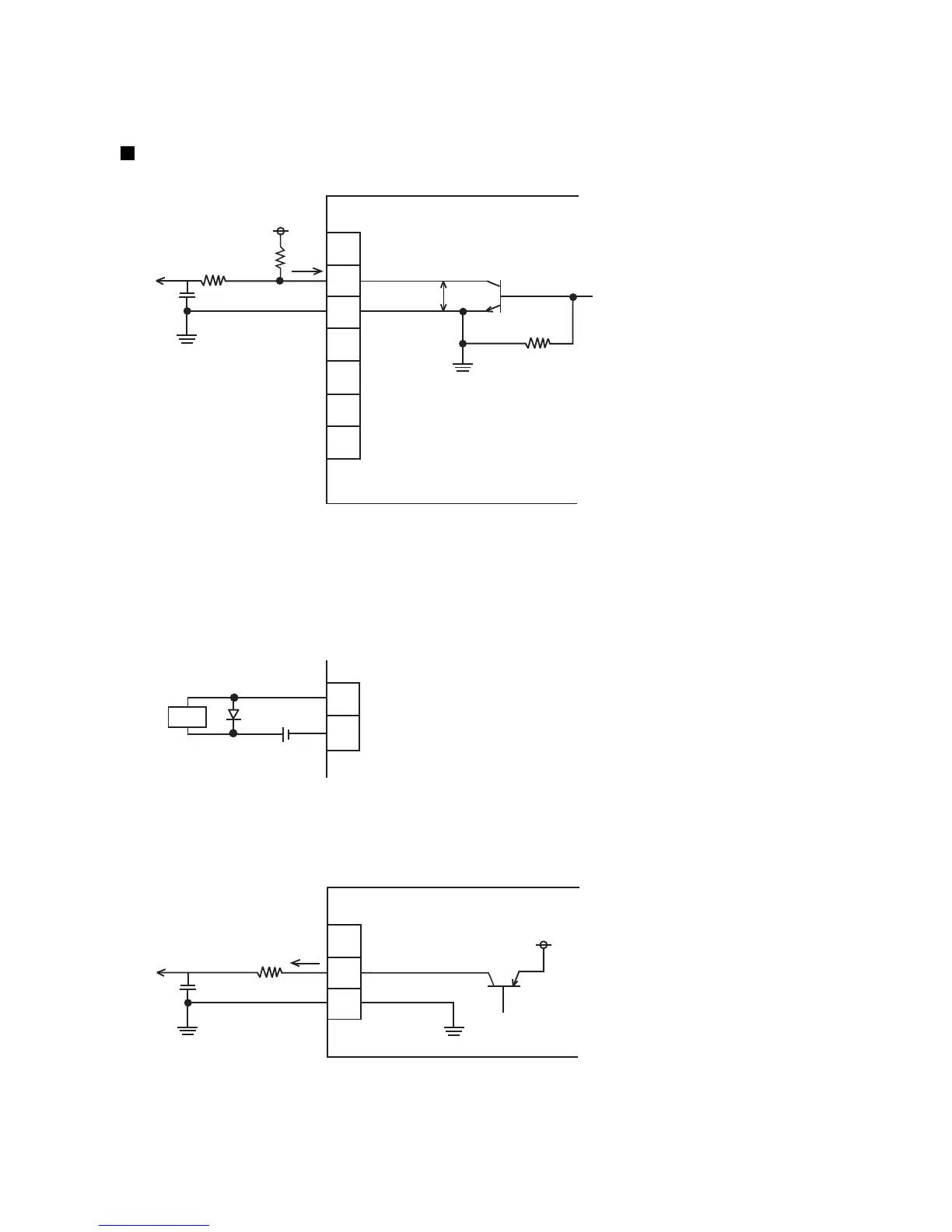
4.3.4 Output function
The state of the IJ printer is monitored by connecting the print output (“Print-in-progress” or “Print.complete”),
online output, Ready, Fault, and Warning signals to pins 10 to 23 of TB1. (No-contact (transistor) output)
Internal circuit diagram
(a) NPN interface output (no-voltage output)
●The output transistor is open collector, and the logic is transistor ON at operation ON.
●The voltage and current used by the external equipment must satisfy the following specifications:
IL 20mA (V
CE : TYP0.6V, MAX2V)
Vd DC30V
●Wiring precautions
<
=
<
=
●When the load is a relay, solenoid, or other inductive load, connect a diode to prevent generation of a
counter electromotive force in parallel with the load.
●The load circuit is DC dedicated. It cannot be used with an AC load.
(b) PNP interface output (voltage output)
●The output transistor is open collector and the logic is transistor ON (voltage output) at operation ON.
●When used with external equipment, the following shall be satisfied:
IL 10mA(V
CE : TYP0.6V, MAX2V), Guide line of R : R 2.2kΩ
Withstand voltage 50VDC or greater (2 times or more of the voltage used)
<
=
>
=

 Loading...