Model IFP-2100/ECS Installation Manual LS10143-001SK-E
4-19
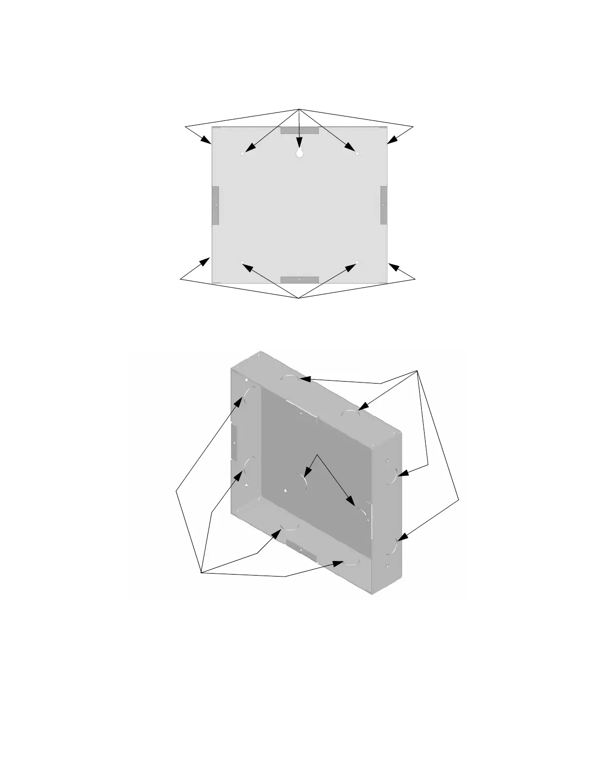
1. The backbox dimensions are 9-9/32” W x 8-3/8” H. The backbox can be mounted prior to the complete
installation of the RA-100 using any of the mounting holes shown in Figure 4-25.
Figure 4-25 Backbox Mounting Holes
2. Remove knockout holes as needed for wires. See Figure 4-26 for backbox knockout locations
Figure 4-26 Backbox Knockout Locations
3. Wire the Annunciator board to the main control panel. See Figure 4-23.
Mounting Holes
Mounting Holes
Wire Knockouts
Wire Knockouts
Wire Knockouts

 Loading...


